
Chapter 14
Airport Operations
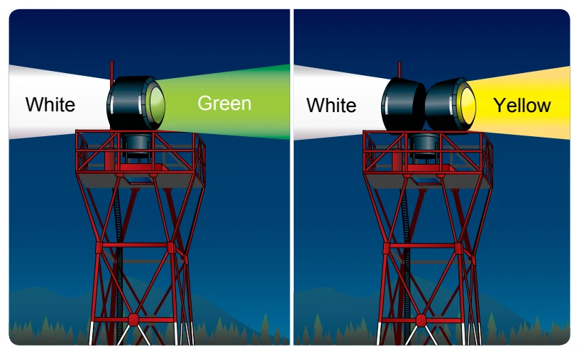
Airport beacons help a pilot identify an airport at night. The beacons are normally operated from dusk until dawn. Sometimes they are turned on if the ceiling is less than 1,000 feet and/or the ground visibility is less than 3 statute miles (VFR minimums). However, there is no requirement for this, so a pilot has the responsibility of determining if the weather meets VFR requirements. The beacon has a vertical light distribution to make it most effective from 1-10° above the horizon, although it can be seen well above or below this spread. The beacon may be an omnidirectional capacitor-discharge device, or it may rotate at a constant speed, that produces the visual effect of flashes at regular intervals. The combination of light colors from an airport beacon indicates the type of airport. [Figure 14-28] Some of the most common beacons are:
- Flashing white and green for civilian land airports
- Flashing white and yellow for a water airport
- Flashing white, yellow, and green for a heliport
- Two quick white flashes alternating with a green flash identifying a military airport
Approach Light Systems
Approach light systems are primarily intended to provide a means to transition from instrument flight to visual flight for landing. The system configuration depends on whether the
runway is a precision or nonprecision instrument runway. Some systems include sequenced flashing lights that appear to the pilot as a ball of light traveling toward the runway at high speed. Approach lights can also aid pilots operating under VFR at night.
Visual Glideslope Indicators
Visual glideslope indicators provide the pilot with glidepath information that can be used for day or night approaches. By maintaining the proper glidepath as provided by the system, a pilot should have adequate obstacle clearance and should touch down within a specified portion of the runway.
Visual Approach Slope Indicator (VASI)
VASI installations are the most common visual glidepath systems in use. The VASI provides obstruction clearance within 10° of the extended runway centerline and up to four nautical miles (NM) from the runway threshold.
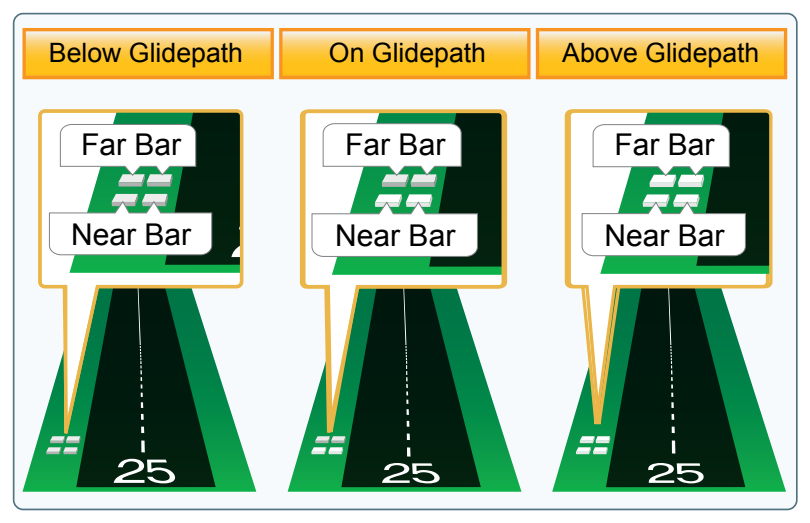
The VASI consists of light units arranged in bars. There are 2-bar and 3-bar VASIs. The 2-bar VASI has near and far light bars and the 3-bar VASI has near, middle, and far light bars. Two-bar VASI installations provide one visual glidepath that is normally set at 3°. The 3-bar system provides two glidepaths, the lower glidepath normally set at 3° and the upper glidepath ¼ degree above the lower glidepath.
The basic principle of the VASI is that of color differentiation between red and white. Each light unit projects a beam of light, a white segment in the upper part of the beam and a red segment in the lower part of the beam. The lights are arranged so the pilot sees the combination of lights shown in
Other Glidepath Systems
A precision approach path indicator (PAPI) uses lights similar to the VASI system, except they are installed in a single row, normally on the left side of the runway. [Figure 14-30]
A tri-color system consists of a single-light unit projecting a three-color visual approach path. Below the glidepath is indicated by red, on the glidepath is indicated by green, and above the glidepath is indicated by amber. When descending below the glidepath, there is a small area of dark amber. Pilots should not mistake this area for an “above the glidepath” indication. [Figure 14-31]
Pulsating VASIs normally consist of a single-light unit projecting a two-color visual approach path into the final approach area of the runway upon which the indicator is installed. The “on glidepath” indication is a steady white light. The “slightly below glidepath” indication is a steady red light. If the aircraft descends further below the glidepath, the red light starts to pulsate. The “above glidepath” indication is a pulsating white light. The pulsating rate increases as the aircraft gets further above or below the desired glideslope. The useful range of the system is about four miles during the day and up to ten miles at night. [Figure 14-32]
Runway Lighting
There are various lights that identify parts of the runway complex. These assist a pilot in safely making a takeoff or landing during night operations.