
Chapter 16
Navigation
Variation is the angle between TN and magnetic north (MN). It is expressed as east variation or west variation depending upon whether MN is to the east or west of TN.
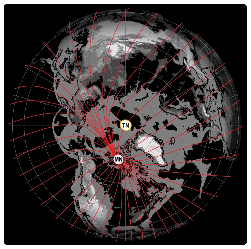
The north magnetic pole is located close to 71° N latitude, 96° W longitude and is about 1,300 miles from the geographic or true north pole, as indicated in Figure 16-8. If the Earth were uniformly magnetized, the compass needle would point toward the magnetic pole, in which case the variation between TN (as shown by the geographical meridians) and MN (as shown by the magnetic meridians) could be measured at any intersection of the meridians.
Actually, the Earth is not uniformly magnetized. In the United States, the needle usually points in the general direction of the magnetic pole, but it may vary in certain geographical localities by many degrees. Consequently, the exact amount of variation at thousands of selected locations in the United States has been carefully determined. The amount and the direction of variation, which change slightly from time to time, are shown on most aeronautical charts as broken magenta lines called isogonic lines that connect points of equal magnetic variation. (The line connecting points at which there is no variation between TN and MN is the agonic line.) An isogonic chart is shown in Figure 16-9. Minor bends and turns in the isogonic and agonic lines are caused by unusual geological conditions affecting magnetic forces in these areas.
On the west coast of the United States, the compass needle points to the east of TN; on the east coast, the compass needle points to the west of TN.
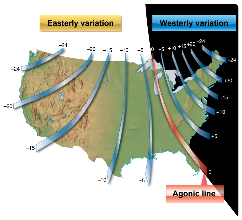
Zero degree variation exists on the agonic line where MN and TN coincide. This line runs roughly west of the Great Lakes, south through Wisconsin, Illinois, western Tennessee, and along the border of Mississippi and Alabama. Compare Figures 16-9 and 16-10.
Because courses are measured in reference to geographical meridians that point toward TN, and these courses are maintained by reference to the compass that points along a magnetic meridian in the general direction of MN, the true direction must be converted into magnetic direction for the purpose of flight. This conversion is made by adding or subtracting the variation indicated by the nearest isogonic line on the chart.
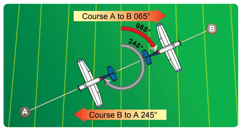
For example, a line drawn between two points on a chart is called a TC as it is measured from TN. However, flying this course off the magnetic compass would not provide an accurate course between the two points due to three elements that must be considered. The first is magnetic variation, the second is compass deviation, and the third is wind correction. All three must be considered for accurate navigation.
Magnetic Variation
As mentioned in the paragraph discussing variation, the appropriate variation for the geographical location of the flight must be considered and added or subtracted as appropriate. If flying across an area where the variation changes, then the values must be applied along the route of flight appropriately. Once applied, this new course is called the magnetic course.
Magnetic Deviation
Because each aircraft has its own internal effect upon the onboard compass systems from its own localized magnetic influencers, the pilot must add or subtract these influencers based upon the direction he or she is flying. The application of deviation (taken from a compass deviation card) compensates the magnetic course unique to that aircraft’s compass system (as affected by localized magnetic influencers) and it now becomes the compass course. Therefore, the compass course, when followed (in a no wind condition), takes the aircraft from point A to point B even though the aircraft heading may not match the original course line drawn on the chart.
If the variation is shown as “9° E,” this means that MN is 9° east of TN. If a TC of 360° is to be flown, 9° must be subtracted from 360°, which results in a magnetic heading of 351°. To fly east, a magnetic course of 081° (090° - 9°) would be flown. To fly south, the magnetic course would be 171° (180° - 9°). To fly west, it would be 261° (270° - 9°). To fly a TH of 060°, a magnetic course of 051° (060° - 9°) would be flown.
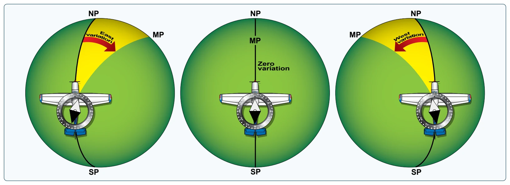
Remember, if variation is west, add; if east, subtract. One method for remembering whether to add or subtract variation is the phrase “east is least (subtract) and west is best (add).”
Deviation
Determining the magnetic heading is an intermediate step necessary to obtain the correct compass heading for the flight. To determine compass heading, a correction for deviation must be made. Because of magnetic influences within an aircraft, such as electrical circuits, radio, lights, tools, engine, and magnetized metal parts, the compass needle is frequently deflected from its normal reading. This deflection is called deviation. The deviation is different for each aircraft, and it also may vary for different headings in the same aircraft. For instance, if magnetism in the engine attracts the north end of the compass, there would be no effect when the plane is on a heading of MN. On easterly or westerly headings, however, the compass indications would be in error, as shown in Figure 16-11. Magnetic attraction can come from many other parts of the aircraft; the assumption of attraction in the engine is merely used for the purpose of illustration.
Some adjustment of the compass, referred to as compensation, can be made to reduce this error, but the remaining correction must be applied by the pilot.