
Chapter 3
Aircraft Construction
Weight is the combined load of the aircraft itself, the crew, the fuel, and the cargo or baggage. Weight pulls the aircraft downward because of the force of gravity. It opposes lift and acts vertically downward through the aircraft’s center of gravity (CG).
Lift opposes the downward force of weight, is produced by the dynamic effect of the air acting on the wing, and acts perpendicular to the flight path through the wing’s center of lift (CL).
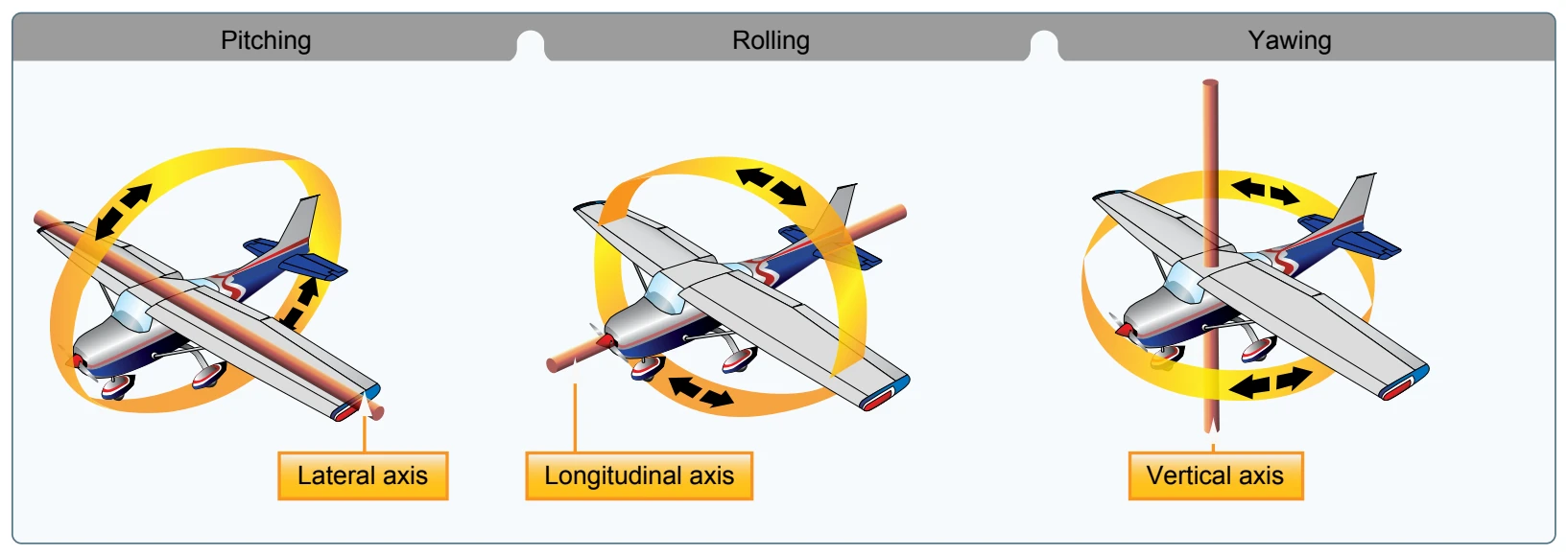
An aircraft moves in three dimensions and is controlled by moving it about one or more of its axes. The longitudinal, or roll, axis extends through the aircraft from nose to tail, with the line passing through the CG. The lateral or pitch axis extends across the aircraft on a line through the wing tips, again passing through the CG. The vertical, or yaw, axis passes through the aircraft vertically, intersecting the CG. All control movements cause the aircraft to move around one or more of these axes and allows for the control of the aircraft in flight. [Figure 3-2]
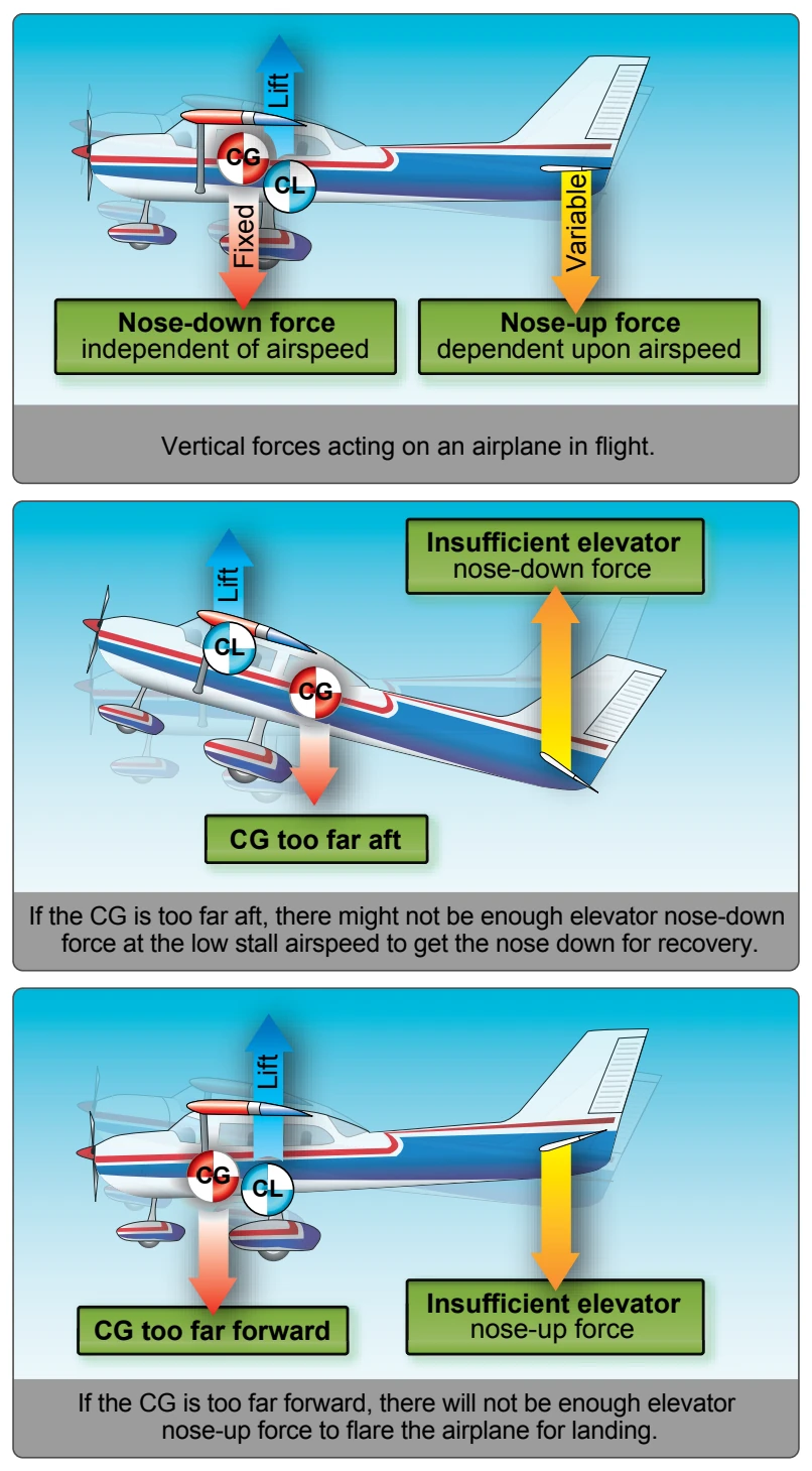
One of the most significant components of aircraft design is CG. It is the specific point where the mass or weight of an aircraft may be said to center; that is, a point around which, if the aircraft could be suspended or balanced, the aircraft would remain relatively level. The position of the CG of an aircraft determines the stability of the aircraft in flight. As the CG moves rearward (towards the tail), the aircraft becomes more and more dynamically unstable. In aircraft with fuel tanks situated in front of the CG, it is important that the CG is set with the fuel tank empty. Otherwise, as the fuel is used, the aircraft becomes unstable. [Figure 3-3] The CG is computed during initial design and construction and is further affected by the installation of onboard equipment, aircraft loading, and other factors.
Major Components
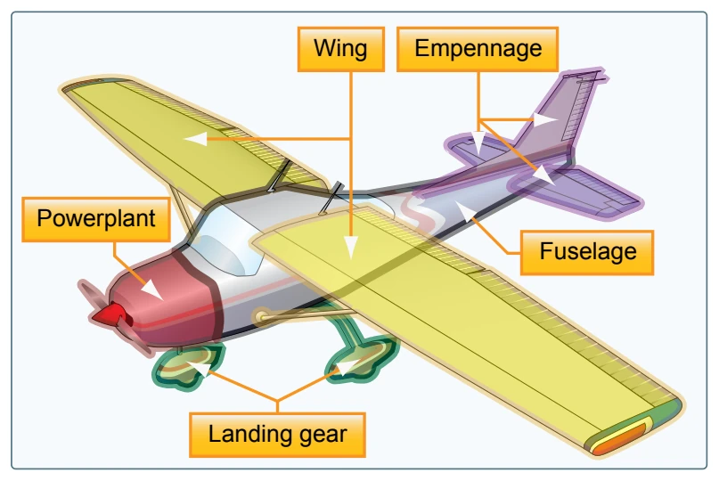
Although airplanes are designed for a variety of purposes, most of them have the same major components. [Figure 3-4] The overall characteristics are largely determined by the original design objectives. Most airplane structures include a fuselage, wings, an empennage, landing gear, and a powerplant.
Fuselage
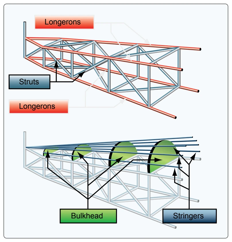
The fuselage is the central body of an airplane and is designed to accommodate the crew, passengers, and cargo. It also provides the structural connection for the wings and tail assembly. Older types of aircraft design utilized an open truss structure constructed of wood, steel, or aluminum tubing. [Figure 3-5] The most popular types of fuselage structures used in today’s aircraft are the monocoque (French for “single shell”) and semimonocoque. These structure types are discussed in more detail under aircraft construction later in the chapter.
Wings
The wings are airfoils attached to each side of the fuselage and are the main lifting surfaces that support the airplane in flight. There are numerous wing designs, sizes, and shapes used by the various manufacturers. Each fulfills a certain need with respect to the expected performance for the particular airplane. How the wing produces lift is explained in Chapter 5, Aerodynamics of Flight.
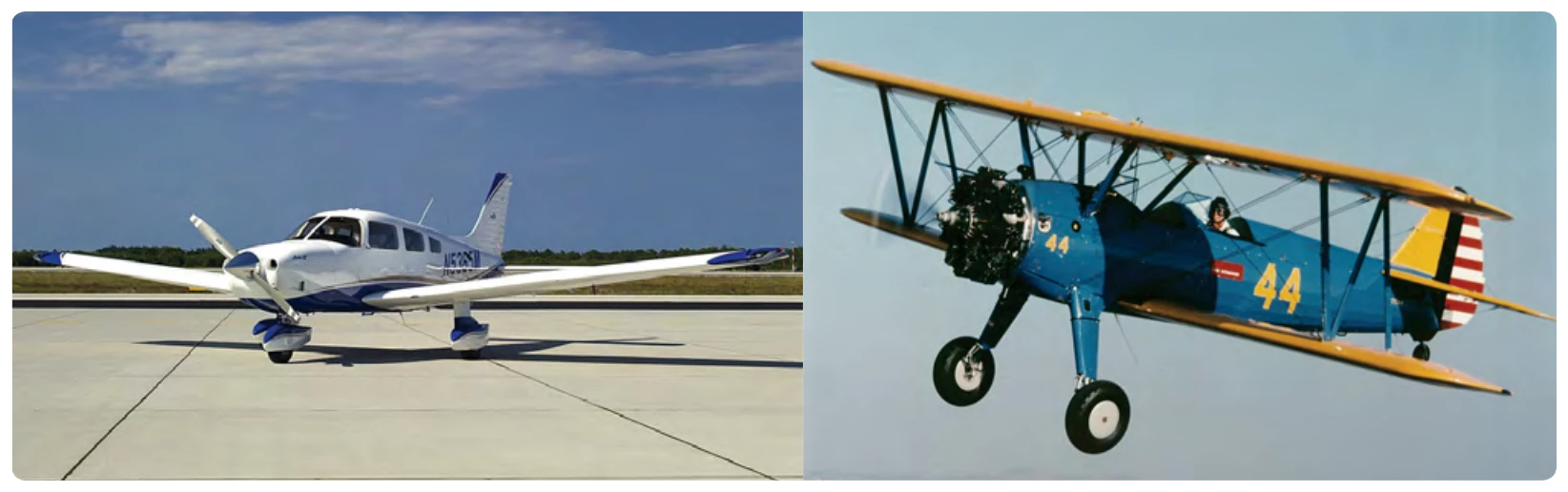
Wings may be attached at the top, middle, or lower portion of the fuselage. These designs are referred to as high-, mid-, and low-wing, respectively. The number of wings can also vary. Airplanes with a single set of wings are referred to as monoplanes, while those with two sets are called biplanes. [Figure 3-6]
Many high-wing airplanes have external braces, or wing struts that transmit the flight and landing loads through the struts to the main fuselage structure. Since the wing struts are usually attached approximately halfway out on the wing, this type of wing structure is called semi-cantilever. A few high-wing and most low-wing airplanes have a full cantilever wing designed to carry the loads without external struts.
The principal structural parts of the wing are spars, ribs, and stringers. [Figure 3-7] These are reinforced by trusses, I-beams, tubing, or other devices, including the skin. The wing ribs determine the shape and thickness of the wing (airfoil). In most modern airplanes, the fuel tanks are either an integral part of the wing’s structure or consist of flexible containers mounted inside of the wing.
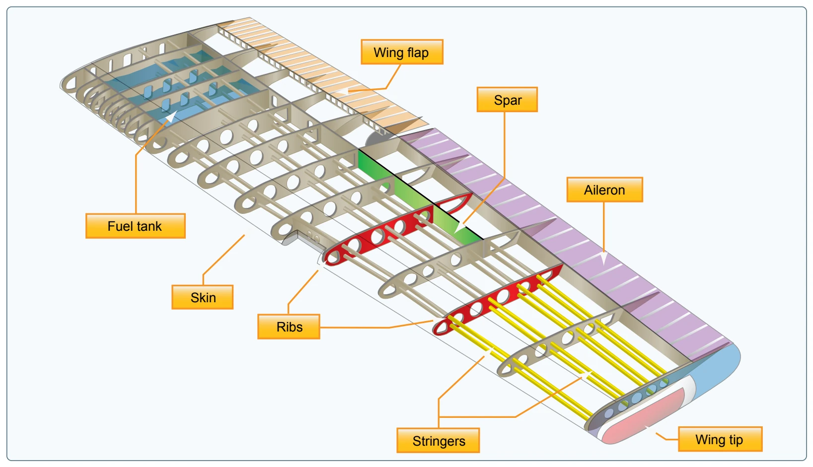
Attached to the rear, or trailing edges, of the wings are two types of control surfaces referred to as ailerons and flaps. Ailerons extend from about the midpoint of each wing outward toward the tip, and move in opposite directions to create aerodynamic forces that cause the airplane to roll. Flaps extend outward from the fuselage to near the midpoint of each wing. The flaps are normally flush with the wing’s surface during cruising flight. When extended, the flaps move simultaneously downward to increase the lifting force of the wing for takeoffs and landings. [Figure 3-8]