Chapter 3
Aircraft Construction
The potential for heat damage to the resin is another disadvantage of using composites. While “too hot” depends on the particular resin system chosen, many epoxies begin to weaken over 150 °F. White paint on composites is often used to minimize this issue. For example, the bottom of a wing that is painted black facing a black asphalt ramp on a hot, sunny day can get as hot as 220 °F. The same structure, painted white, rarely exceeds 140 °F. As a result, composite aircraft often have specific recommendations on allowable paint colors. If the aircraft is repainted, these recommendations must be followed. Heat damage can also occur due to a fire. Even a quickly extinguished small brake fire can damage bottom wing skins, composite landing gear legs, or wheel pants.
Also, chemical paint strippers are very harmful to composites and must not be used on them. If paint needs to be removed from composites, only mechanical methods are allowed, such as gentle grit blasting or sanding. Many expensive composite parts have been ruined by the use of paint stripper and such damage is generally not repairable.
Fluid Spills on Composites
Some owners are concerned about fuel, oil, or hydraulic fluid spills on composite surfaces. These are generally not a problem with modern composites using epoxy resin. Usually, if the spill does not attack the paint, it will not hurt the underlying composite. Some aircraft use fiberglass fuel tanks, for example, in which the fuel rides directly against the composite surface with no sealant being used. If the fiberglass structure is made with some of the more inexpensive types of polyester resin, there can be a problem when using auto gas with ethanol blended into the mixture. The more expensive types of polyester resin, as well as epoxy resin, can be used with auto gas, as well as 100 octane aviation gas (avgas) and jet fuel.
Lightning Strike Protection
Lightning strike protection is an important consideration in aircraft design. When an aircraft is hit by lightning, a very large amount of energy is delivered to the structure. Whether flying a light general aviation (GA) aircraft or a large airliner, the basic principle of lightning strike protection is the same. For any size aircraft, the energy from the strike must be spread over a large surface area to lower the amps per square inch to a harmless level.
If lightning strikes an aluminum airplane, the electrical energy naturally conducts easily through the aluminum structure. The challenge is to keep the energy out of avionics, fuel systems, etc., until it can be safely conducted overboard. The outer skin of the aircraft is the path of least resistance.
In a composite aircraft, fiberglass is an excellent electrical insulator, while carbon fiber conducts electricity, but not as easily as aluminum. Therefore, additional electrical conductivity needs to be added to the outside layer of composite skin. This is done typically with fine metal meshes bonded to the skin surfaces. Aluminum and copper mesh are the two most common types, with aluminum used on fiberglass and copper on carbon fiber. Any structural repairs on lightning-strike protected areas must also include the mesh as well as the underlying structure.
For composite aircraft with internal radio antennas, there must be “windows” in the lightning strike mesh in the area of the antenna. Internal radio antennas may be found in fiberglass composites because fiberglass is transparent to radio frequencies, where carbon fiber is not.
The Future of Composites
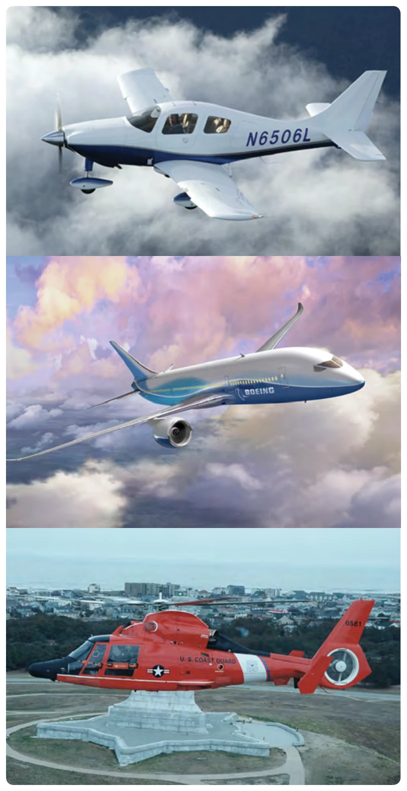
In the decades since World War II, composites have earned an important role in aircraft structure design. Their design flexibility and corrosion resistance, as well as the high strength-to-weight ratios possible, will undoubtedly continue to lead to more innovative aircraft designs in the future. From the Cirrus SR-20 to the Boeing 787, it is obvious that composites have found a home in aircraft construction and are here to stay. [Figure 3-17]
Instrumentation: Moving into the Future
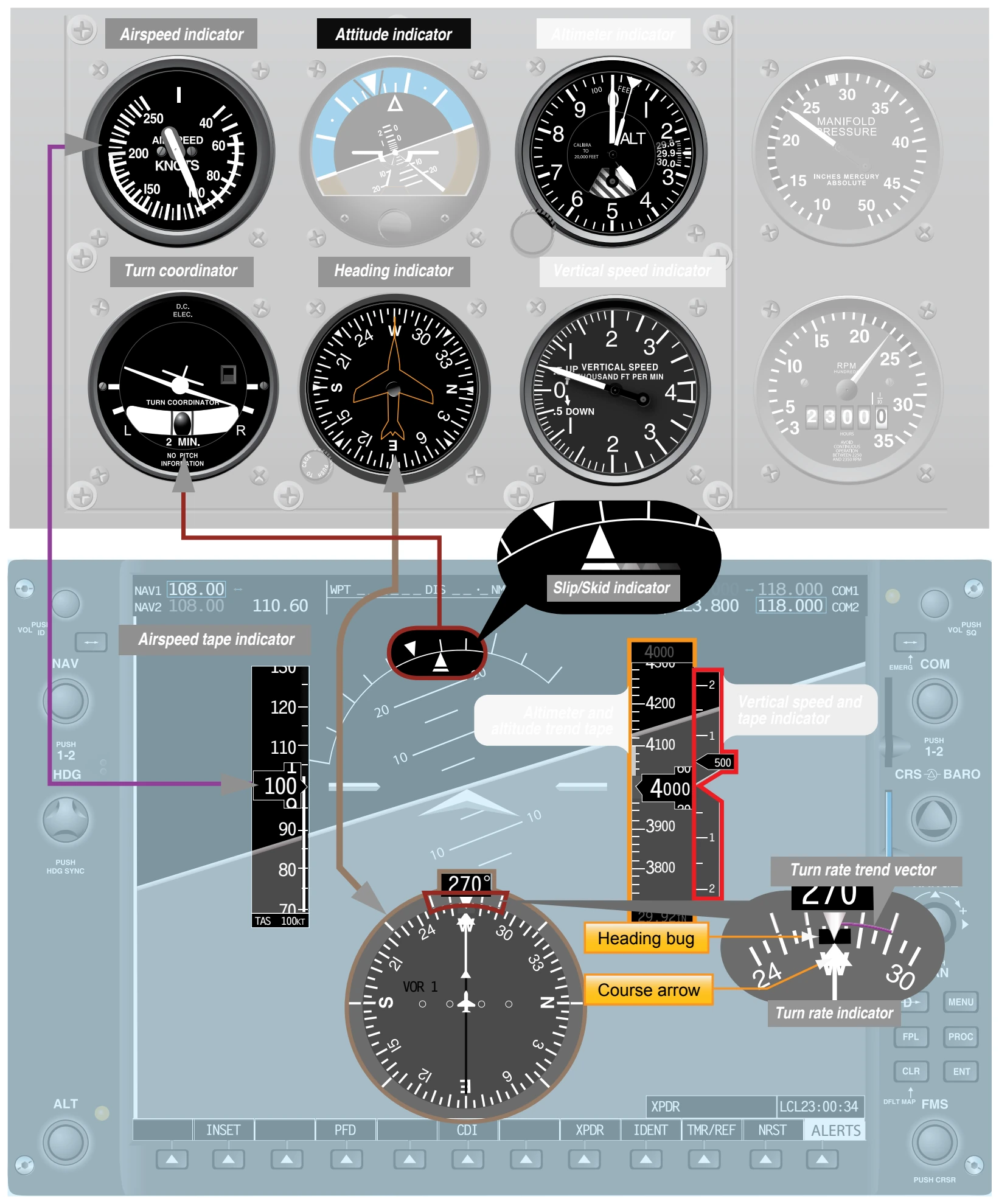
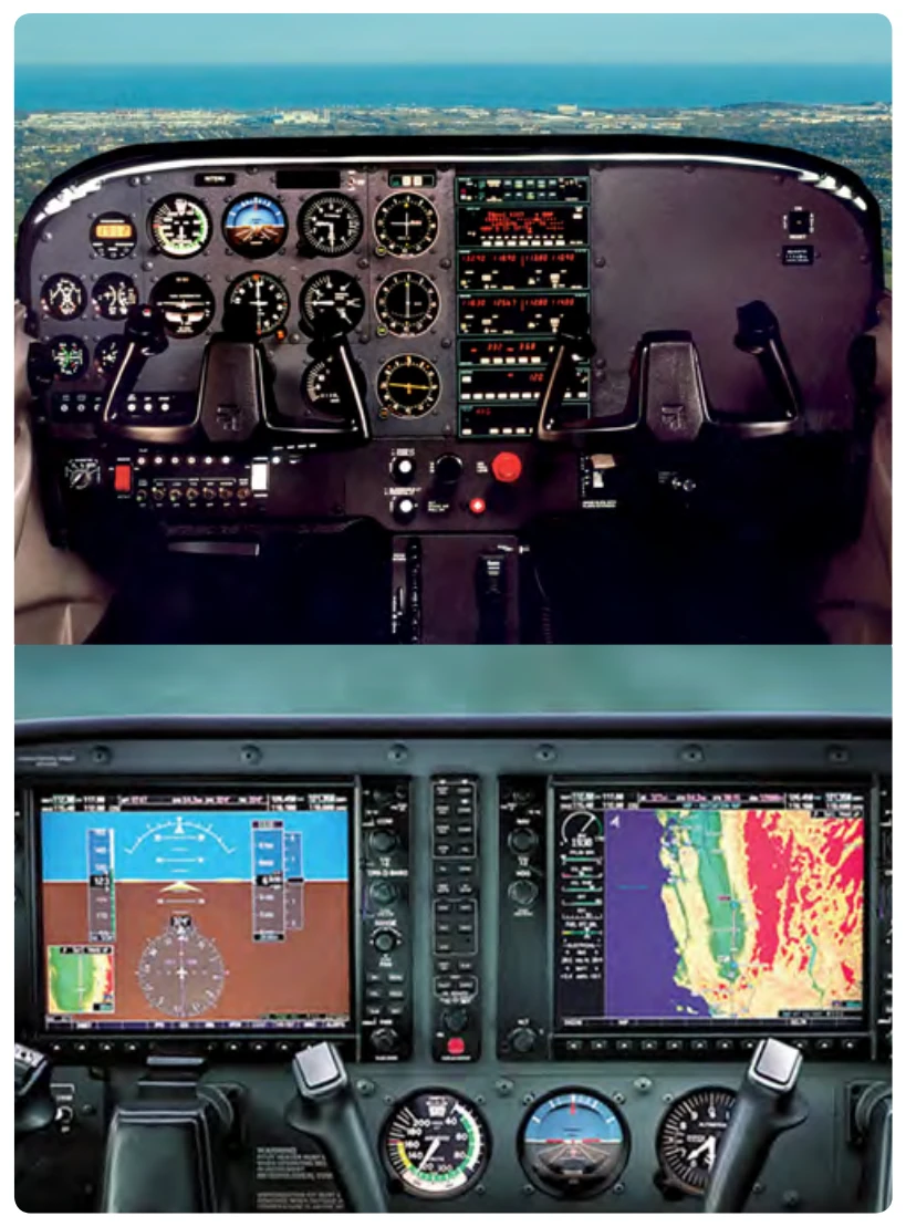
Until recently, most GA aircraft were equipped with individual instruments utilized collectively to safely operate and maneuver the aircraft. With the release of the electronic flight display (EFD) system, conventional instruments have been replaced by multiple liquid crystal display (LCD) screens. The first screen is installed in front of the pilot position and is referred to as the primary flight display (PFD). The second screen, positioned approximately in the center of the instrument panel, is referred to as the multi-function display (MFD). These two screens de-clutter instrument panels while increasing safety. This has been accomplished through the utilization of solid state instruments that have a failure rate far less than those of conventional analog instrumentation. [Figure 3-18]
With today’s improvements in avionics and the introduction of EFDs, pilots at any level of experience need an astute knowledge of the onboard flight control systems, as well as an understanding of how automation melds with aeronautical decision-making (ADM). These subjects are covered in detail in Chapter 2, Aeronautical Decision-Making.
Whether an aircraft has analog or digital (glass) instruments, the instrumentation falls into three different categories: performance, control, and navigation.
Performance Instruments
The performance instruments indicate the aircraft’s actual performance. Performance is determined by reference to the altimeter, airspeed or vertical speed indicator (VSI), heading indicator, and turn-and-slip indicator. The performance instruments directly reflect the performance the aircraft is achieving. The speed of the aircraft can be referenced on the airspeed indicator. The altitude can be referenced on the altimeter. The aircraft’s climb performance can be determined by referencing the VSI. Other performance instruments available are the heading indicator, angle of attack indicator, and the slip-skid indicator. [Figure 3-19]