
Chapter 5
Aerodynamics of Flight
The coefficient of lift is dimensionless and relates the lift generated by a lifting body, the dynamic pressure of the fluid flow around the body, and a reference area associated with the body. The coefficient of drag is also dimensionless and is used to quantify the drag of an object in a fluid environment, such as air, and is always associated with a particular surface area.
The L/D ratio is determined by dividing the CL by the CD, which is the same as dividing the lift equation by the drag equation as all of the variables, aside from the coefficients, cancel out. The lift and drag equations are as follows (L = Lift in pounds; D = Drag; CL = coefficient of lift; ρ = density (expressed in slugs per cubic feet); V = velocity (in feet per second); q = dynamic pressure per square foot (q = 1⁄2 ρv2); S = the area of the lifting body (in square feet); and CD = Ratio of drag pressure to dynamic pressure):
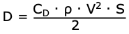
Typically at low AOA, the coefficient of drag is low and small changes in AOA create only slight changes in the coefficient of drag. At high AOA, small changes in the AOA cause significant changes in drag. The shape of an airfoil, as well as changes in the AOA, affects the production of lift.
Notice in Figure 5-5 that the coefficient of lift curve (red) reaches its maximum for this particular wing section at 20° AOA and then rapidly decreases. 20° AOA is therefore the critical angle of attack. The coefficient of drag curve (orange) increases very rapidly from 14° AOA and completely overcomes the lift curve at 21° AOA. The lift/drag ratio (green) reaches its maximum at 6° AOA, meaning that at this angle, the most lift is obtained for the least amount of drag.
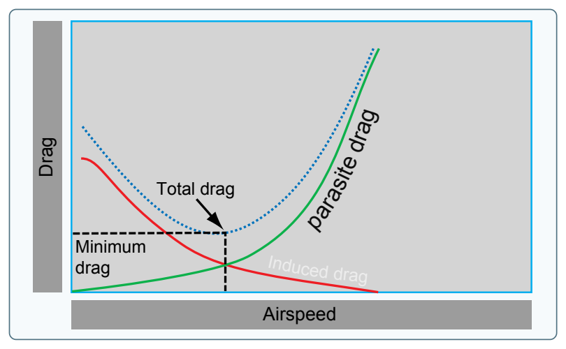
Note that the maximum lift/drag ratio (L/DMAX) occurs at one specific CL and AOA. If the aircraft is operated in steady flight at L/DMAX, the total drag is at a minimum. Any AOA lower or higher than that for L/DMAX reduces the L/D and consequently increases the total drag for a given aircraft’s lift. Figure 5-6 depicts the L/DMAX by the lowest portion of the blue line labeled “total drag.” The configuration of an aircraft has a great effect on the L/D.
Drag
Drag is the force that resists movement of an aircraft through the air. There are two basic types: parasite drag and induced drag. The first is called parasite because it in no way functions to aid flight, while the second, induced drag, is a result of an airfoil developing lift.
Parasite Drag
Parasite drag is comprised of all the forces that work to slow an aircraft’s movement. As the term parasite implies, it is the drag that is not associated with the production of lift. This includes the displacement of the air by the aircraft, turbulence generated in the airstream, or a hindrance of air moving over the surface of the aircraft and airfoil. There are three types of parasite drag: form drag, interference drag, and skin friction.
Form Drag
Form drag is the portion of parasite drag generated by the aircraft due to its shape and airflow around it. Examples include the engine cowlings, antennas, and the aerodynamic shape of other components. When the air has to separate to move around a moving aircraft and its components, it eventually rejoins after passing the body. How quickly and smoothly it rejoins is representative of the resistance that it creates, which requires additional force to overcome. [Figure 5-7]
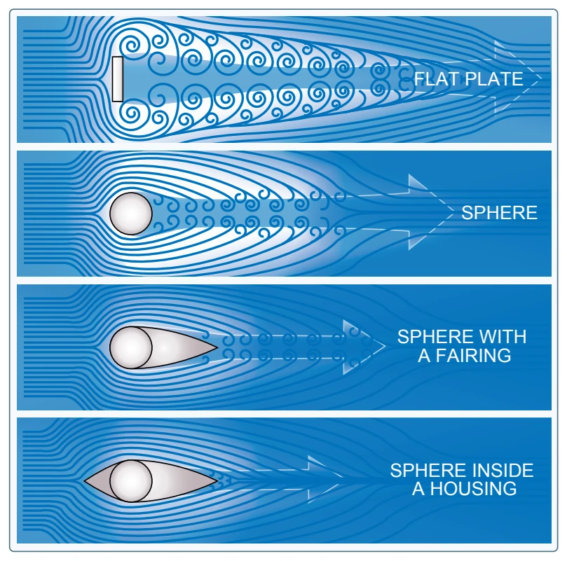
Notice how the flat plate in Figure 5-7 causes the air to swirl around the edges until it eventually rejoins downstream. Form drag is the easiest to reduce when designing an aircraft. The solution is to streamline as many of the parts as possible.
Interference Drag
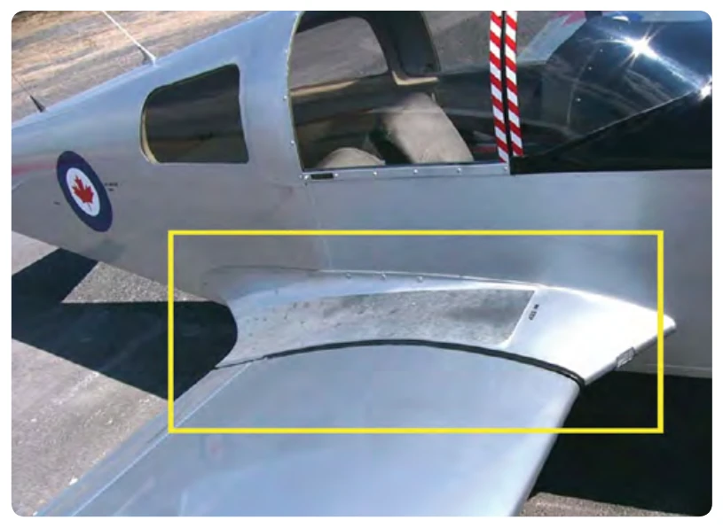
Interference drag comes from the intersection of airstreams that creates eddy currents, turbulence, or restricts smooth airflow. For example, the intersection of the wing and the fuselage at the wing root has significant interference drag. Air flowing around the fuselage collides with air flowing over the wing, merging into a current of air different from the two original currents. The most interference drag is observed when two surfaces meet at perpendicular angles. Fairings are used to reduce this tendency. If a jet fighter carries two identical wing tanks, the overall drag is greater than the sum of the individual tanks because both of these create and generate interference drag. Fairings and distance between lifting surfaces and external components (such as radar antennas hung from wings) reduce interference drag. [Figure 5-8]
Skin Friction Drag
Skin friction drag is the aerodynamic resistance due to the contact of moving air with the surface of an aircraft. Every surface, no matter how apparently smooth, has a rough, ragged surface when viewed under a microscope. The air molecules, which come in direct contact with the surface of the wing, are virtually motionless. Each layer of molecules above the surface moves slightly faster until the molecules are moving at the velocity of the air moving around the aircraft. This speed is called the free-stream velocity. The area between the wing and the free-stream velocity level is about as wide as a playing card and is called the boundary layer. At the top of the boundary layer, the molecules increase velocity and move at the same speed as the molecules outside the boundary layer. The actual speed at which the molecules move depends upon the shape of the wing, the viscosity (stickiness) of the air through which the wing or airfoil is moving, and its compressibility (how much it can be compacted).