
Chapter 7
Aircraft Systems
Some aircraft have receptacles to which an external ground power unit (GPU) may be connected to provide electrical energy for starting. These are very useful, especially during cold weather starting. Follow the manufacturer’s recommendations for engine starting using a GPU.
The electrical system is turned on or off with a master switch. Turning the master switch to the ON position provides electrical energy to all the electrical equipment circuits except the ignition system. Equipment that commonly uses the electrical system for its source of energy includes:
- Position lights
- Anticollision lights
- Landing lights
- Taxi lights
- Interior cabin lights
- Instrument lights
- Radio equipment
- Turn indicator
- Fuel gauges
- Electric fuel pump
- Stall warning system
- Pitot heat
- Starting motor
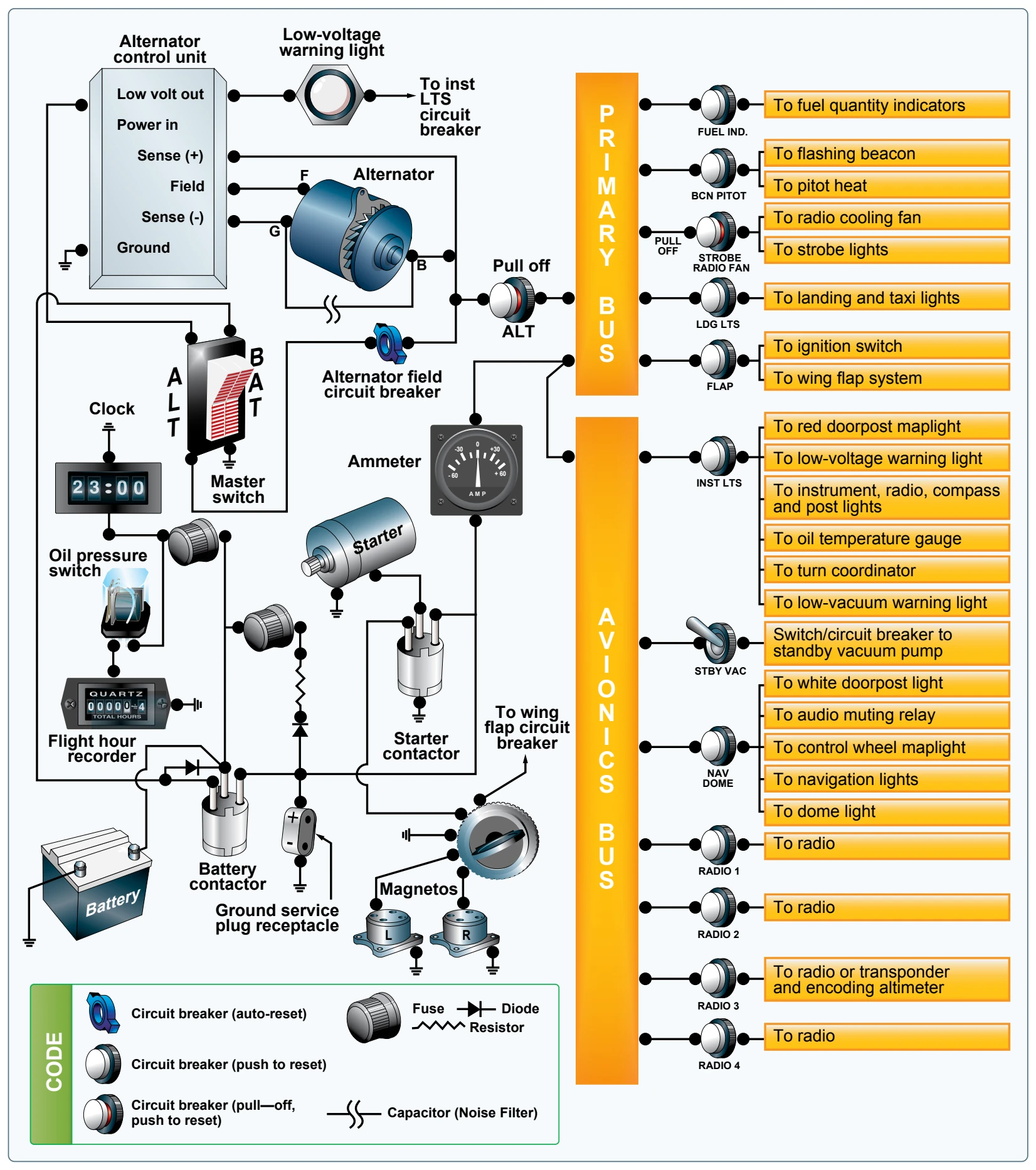
Many aircraft are equipped with a battery switch that controls the electrical power to the aircraft in a manner similar to the master switch. In addition, an alternator switch is installed that permits the pilot to exclude the alternator from the electrical system in the event of alternator failure. [Figure 7-33]
With the alternator half of the switch in the OFF position, the entire electrical load is placed on the battery. All nonessential electrical equipment should be turned off to conserve battery power.
A bus bar is used as a terminal in the aircraft electrical system to connect the main electrical system to the equipment using electricity as a source of power. This simplifies the wiring system and provides a common point from which voltage can be distributed throughout the system. [Figure 7-34]
Fuses or circuit breakers are used in the electrical system to protect the circuits and equipment from electrical overload. Spare fuses of the proper amperage limit should be carried in the aircraft to replace defective or blown fuses. Circuit breakers have the same function as a fuse but can be manually reset, rather than replaced, if an overload condition occurs in the electrical system. Placards at the fuse or circuit breaker panel identify the circuit by name and show the amperage limit.
![On this master switch, the left half is for the alternator and the right half is for the battery. [Figure 7-36]](https://aviationtrainingexperts.com/images/library/phak/faa-pilots-handbook-figure-7-33-on-this-master-switch-the-left-half-is-for-the-alternator-and-the-right.webp)
An ammeter is used to monitor the performance of the aircraft electrical system. The ammeter shows if the alternator/ generator is producing an adequate supply of electrical power. It also indicates whether or not the battery is receiving an electrical charge.
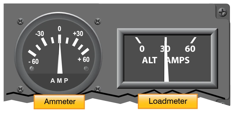
Ammeters are designed with the zero point in the center of the face and a negative or positive indication on either side. [Figure 7-35] When the pointer of the ammeter is on the plus side, it shows the charging rate of the battery. A minus indication means more current is being drawn from the battery than is being replaced. A full-scale minus deflection indicates a malfunction of the alternator/generator. A full-scale positive deflection indicates a malfunction of the regulator. In either case, consult the AFM/POH for appropriate action to be taken.
Not all aircraft are equipped with an ammeter. Some have a warning light that, when lighted, indicates a discharge in the system as a generator/alternator malfunction. Refer to the AFM/POH for appropriate action to be taken.
Another electrical monitoring indicator is a loadmeter. This type of gauge has a scale beginning with zero and shows the load being placed on the alternator/generator. [Figure 7-35] The loadmeter reflects the total percentage of the load placed on the generating capacity of the electrical system by the electrical accessories and battery. When all electrical components are turned off, it reflects only the amount of charging current demanded by the battery.
A voltage regulator controls the rate of charge to the battery by stabilizing the generator or alternator electrical output. The generator/alternator voltage output should be higher than the battery voltage. For example, a 12-volt battery would be fed by a generator/alternator system of approximately 14 volts. The difference in voltage keeps the battery charged.
Hydraulic Systems
There are multiple applications for hydraulic use in aircraft, depending on the complexity of the aircraft. For example, a hydraulic system is often used on small airplanes to operate wheel brakes, retractable landing gear, and some constant-speed propellers. On large airplanes, a hydraulic system is used for flight control surfaces, wing flaps, spoilers, and other systems.
A basic hydraulic system consists of a reservoir, pump (either hand, electric, or engine-driven), a filter to keep the fluid clean, a selector valve to control the direction of flow, a relief valve to relieve excess pressure, and an actuator. [Figure 7-36]
The hydraulic fluid is pumped through the system to an actuator or servo. A servo is a cylinder with a piston inside that turns fluid power into work and creates the power needed to move an aircraft system or flight control. Servos can be either single-acting or double-acting, based on the needs of the system. This means that the fluid can be applied to one or both sides of the servo, depending on the servo type. A single-acting servo provides power in one direction. The selector valve allows the fluid direction to be controlled. This is necessary for operations such as the extension and retraction of landing gear during which the fluid must work in two different directions. The relief valve provides an outlet
for the system in the event of excessive fluid pressure in the system. Each system incorporates different components to meet the individual needs of different aircraft.