
Chapter 7
Aircraft Systems
The cruise propeller has a higher pitch, therefore more drag. More drag results in lower rpm and less horsepower capability, which decreases performance during takeoffs and climbs but increases efficiency during cruising flight.
The propeller is usually mounted on a shaft, which may be an extension of the engine crankshaft. In this case, the rpm of the propeller would be the same as the crankshaft rpm. On some engines, the propeller is mounted on a shaft geared to the engine crankshaft. In this type, the rpm of the propeller is different than that of the engine.
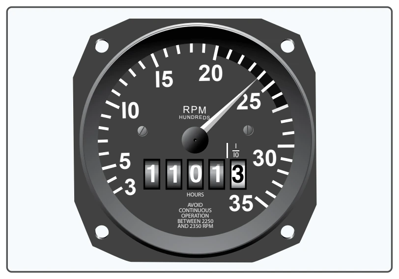
In a fixed-pitch propeller, the tachometer is the indicator of engine power. [Figure 7-8] A tachometer is calibrated in hundreds of rpm and gives a direct indication of the engine and propeller rpm. The instrument is color coded with a green arc denoting the maximum continuous operating rpm. Some tachometers have additional markings to reflect engine and/or propeller limitations. The manufacturer’s recommendations should be used as a reference to clarify any misunderstanding of tachometer markings.
The rpm is regulated by the throttle, which controls the fuel-air flow to the engine. At a given altitude, the higher the tachometer reading, the higher the power output of the engine.
When operating altitude increases, the tachometer may not show correct power output of the engine. For example, 2,300 rpm at 5,000 feet produces less horsepower than 2,300 rpm at sea level because power output depends on air density. Air density decreases as altitude increases and a decrease in air
density (higher density altitude) decreases the power output of the engine. As altitude changes, the position of the throttle must be changed to maintain the same rpm. As altitude is increased, the throttle must be opened further to indicate the same rpm as at a lower altitude.
Adjustable-Pitch Propeller
The adjustable-pitch propeller was the forerunner of the constant-speed propeller. It is a propeller with blades whose pitch can be adjusted on the ground with the engine not running, but which cannot be adjusted in flight. It is also referred to as a ground adjustable propeller. By the 1930s, pioneer aviation inventors were laying the ground work for automatic pitch-change mechanisms, which is why the term sometimes refers to modern constant-speed propellers that are adjustable in flight.
The first adjustable-pitch propeller systems provided only two pitch settings: low and high. Today, most adjustable-pitch propeller systems are capable of a range of pitch settings.
A constant-speed propeller is a controllable-pitch propeller whose pitch is automatically varied in flight by a governor maintaining constant rpm despite varying air loads. It is the most common type of adjustable-pitch propeller. The main advantage of a constant-speed propeller is that it converts a high percentage of brake horsepower (BHP) into thrust horsepower (THP) over a wide range of rpm and airspeed combinations. A constant-speed propeller is more efficient than other propellers because it allows selection of the most efficient engine rpm for the given conditions.
An aircraft with a constant-speed propeller has two controls: the throttle and the propeller control. The throttle controls power output, and the propeller control regulates engine rpm. This regulates propeller rpm, which is registered on the tachometer.
Once a specific rpm is selected, a governor automatically adjusts the propeller blade angle as necessary to maintain the selected rpm. For example, after setting the desired rpm during cruising flight, an increase in airspeed or decrease in propeller load causes the propeller blade angle to increase as necessary to maintain the selected rpm. A reduction in airspeed or increase in propeller load causes the propeller blade angle to decrease.
The propeller’s constant-speed range, defined by the high and low pitch stops, is the range of possible blade angles for a constant-speed propeller. As long as the propeller blade angle is within the constant-speed range and not against either pitch stop, a constant engine rpm is maintained. If the propeller blades contact a pitch stop, the engine rpm will increase or decrease as appropriate, with changes in airspeed and propeller load. For example, once a specific rpm has been selected, if aircraft speed decreases enough to rotate the propeller blades until they contact the low pitch stop, any further decrease in airspeed will cause engine rpm to decrease the same way as if a fixed-pitch propeller were installed. The same holds true when an aircraft equipped with a constant-speed propeller accelerates to a faster airspeed. As the aircraft accelerates, the propeller blade angle increases to maintain the selected rpm until the high pitch stop is reached. Once this occurs, the blade angle cannot increase any further and engine rpm increases.
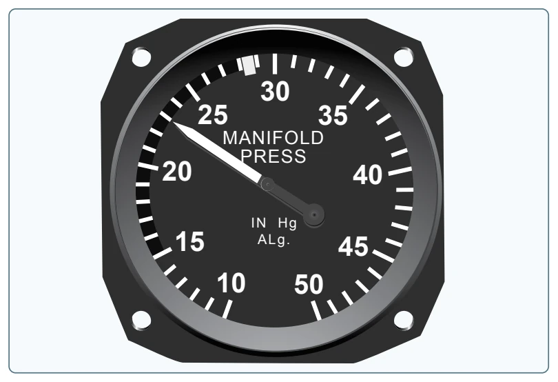
On aircraft equipped with a constant-speed propeller, power output is controlled by the throttle and indicated by a manifold pressure gauge. The gauge measures the absolute pressure of the fuel-air mixture inside the intake manifold and is more correctly a measure of manifold absolute pressure (MAP). At a constant rpm and altitude, the amount of power produced is directly related to the fuel-air mixture being delivered to the combustion chamber. As the throttle setting is increased, more fuel and air flows to the engine and MAP increases. When the engine is not running, the manifold pressure gauge indicates ambient air pressure (i.e., 29.92 inches mercury (29.92 "Hg)). When the engine is started, the manifold pressure indication decreases to a value less than ambient pressure (i.e., idle at 12 "Hg). Engine failure or power loss is indicated on the manifold gauge as an increase in manifold pressure to a value corresponding to the ambient air pressure at the altitude where the failure occurred. [Figure 7-9]
The manifold pressure gauge is color coded to indicate the engine’s operating range. The face of the manifold pressure gauge contains a green arc to show the normal operating range and a red radial line to indicate the upper limit of manifold pressure.
For any given rpm, there is a manifold pressure that should not be exceeded. If manifold pressure is excessive for a given rpm, the pressure within the cylinders could be exceeded, placing undue stress on the cylinders. If repeated too frequently, this stress can weaken the cylinder components and eventually cause engine failure.
A pilot can avoid conditions that overstress the cylinders by being constantly aware of the rpm, especially when increasing the manifold pressure. Consult the manufacturer’s recommendations for power settings of a particular engine to maintain the proper relationship between manifold pressure and rpm.
When both manifold pressure and rpm need to be changed, avoid engine overstress by making power adjustments in the proper order: