Chapter 8
Flight Instruments
Types of Altitude
Altitude in itself is a relevant term only when it is specifically stated to which type of altitude a pilot is referring. Normally when the term “altitude” is used, it is referring to altitude above sea level since this is the altitude which is used to depict obstacles and airspace, as well as to separate air traffic.
Altitude is vertical distance above some point or level used as a reference. There are as many kinds of altitude as there are reference levels from which altitude is measured, and each may be used for specific reasons. Pilots are mainly concerned with five types of altitudes:
- Indicated altitude-read directly from the altimeter (uncorrected) when it is set to the current altimeter setting.
- True altitude-the vertical distance of the aircraft above sea level-the actual altitude. It is often expressed as feet above mean sea level (MSL). Airport, terrain, and obstacle elevations on aeronautical charts are true altitudes.
- Absolute altitude-the vertical distance of an aircraft above the terrain, or above ground level (AGL).
- Pressure altitude-the altitude indicated when the altimeter setting window (barometric scale) is adjusted to 29.92 "Hg. This is the altitude above the standard datum plane, which is a theoretical plane where air pressure (corrected to 15 °C) equals 29.92 "Hg. Pressure altitude is used to compute density altitude, true altitude, true airspeed (TAS), and other performance data.
- Density altitude-pressure altitude corrected for variations from standard temperature. When conditions are standard, pressure altitude and density altitude are the same. If the temperature is above standard, the density altitude is higher than pressure altitude. If the temperature is below standard, the density altitude is lower than pressure altitude. This is an important altitude because it is directly related to the aircraft’s performance.
A pilot must understand how the performance of the aircraft is directly related to the density of the air. The density of the air affects how much power a naturally aspirated engine produces, as well as how efficient the airfoils are. If there are fewer air molecules (lower pressure) to accelerate through the propeller, the acceleration to rotation speed is longer and thus produces a longer takeoff roll, which translates to a decrease in performance.
As an example, consider an airport with a field elevation of 5,048 feet MSL where the standard temperature is 5 °C. Under these conditions, pressure altitude and density altitude are the same-5,048 feet. If the temperature changes to 30 °C, the density altitude increases to 7,855 feet. This means an aircraft would perform on takeoff as though the field elevation were 7,855 feet at standard temperature. Conversely, a temperature of -25 °C would result in a density altitude of 1,232 feet. An aircraft would perform much better under these conditions.
Instrument Check
Prior to each flight, a pilot should examine the altimeter for proper indications in order to verify its validity. To determine the condition of an altimeter, set the barometric scale to the current reported altimeter setting transmitted by the local airport traffic control tower, flight service station (FSS), or any other reliable source, such as ATIS, AWOS, or ASOS. The altimeter pointers should indicate the surveyed field elevation of the airport. If the indication is off more than 75 feet from the surveyed field elevation, the instrument should be referred to a certificated instrument repair station for recalibration.
Vertical Speed Indicator (VSI)
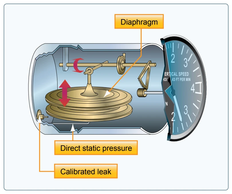
The VSI, which is sometimes called a vertical velocity indicator (VVI), indicates whether the aircraft is climbing, descending, or in level flight. The rate of climb or descent is indicated in feet per minute (fpm). If properly calibrated, the VSI indicates zero in level flight. [Figure 8-5]
Principle of Operation
Although the VSI operates solely from static pressure, it is a differential pressure instrument. It contains a diaphragm with connecting linkage and gearing to the indicator pointer inside an airtight case. The inside of the diaphragm is connected directly to the static line of the pitot-static system. The area outside the diaphragm, which is inside the instrument case, is also connected to the static line but through a restricted orifice (calibrated leak).
Both the diaphragm and the case receive air from the static line at existing atmospheric pressure. The diaphragm receives unrestricted air, while the case receives the static pressure via the metered leak. When the aircraft is on the ground or in level flight, the pressures inside the diaphragm and the instrument case are equal, and the pointer is at the zero indication. When the aircraft climbs or descends, the pressure inside the diaphragm changes immediately, but due to the metering action of the restricted passage, the case pressure remains higher or lower for a short time, causing the diaphragm to contract or expand. This causes a pressure differential that is indicated on the instrument needle as a climb or descent. When the pressure differential stabilizes at a definite ratio, the needle indicates the rate of altitude change.
The VSI displays two different types of information:
- Trend information shows an immediate indication of an increase or decrease in the aircraft’s rate of climb or descent.
- Rate information shows a stabilized rate of change in altitude.
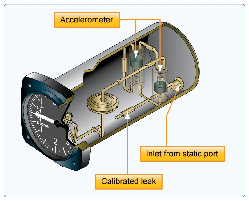
The trend information is the direction of movement of the VSI needle. For example, if an aircraft is maintaining level flight and the pilot pulls back on the control yoke causing the nose of the aircraft to pitch up, the VSI needle moves upward to indicate a climb. If the pitch attitude is held constant, the needle stabilizes after a short period (6-9 seconds) and indicates the rate of climb in hundreds of fpm. The time period from the initial change in the rate of climb, until the VSI displays an accurate indication of the new rate, is called the lag. Rough control technique and turbulence can extend the lag period and cause erratic and unstable rate indications. Some aircraft are equipped with an instantaneous vertical speed indicator (IVSI), which incorporates accelerometers to compensate for the lag in the typical VSI. [Figure 8-6]
Instrument Check
As part of a preflight check, proper operation of the VSI must be established. Make sure the VSI indicates a near zero reading prior to leaving the ramp area and again just before takeoff. If the VSI indicates anything other than zero, that indication can be referenced as the zero mark. Normally, if the needle is not exactly zero, it is only slightly above or below the zero line. After takeoff, the VSI should trend upward to indicate a positive rate of climb and then, once a stabilized climb is established, a rate of climb can be referenced.