
Chapter 9
Flight Manuals and Other Documents
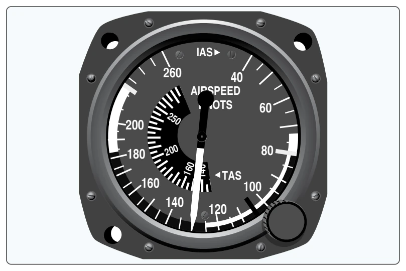
In addition to the markings listed above, small multi-engine airplanes have a red radial line to indicate single-engine minimum controllable airspeed (VMC ). A blue radial line is used to indicate single-engine best rate of climb speed at maximum weight at sea level (VYSE ). [Figure 9-2]
Powerplant
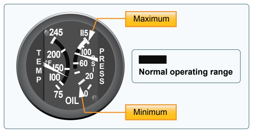
The Powerplant Limitations portion describes operating limitations on an aircraft’s reciprocating or turbine engine(s). These include limitations for takeoff power, maximum continuous power, and maximum normal operating power, which is the maximum power the engine can produce without any restrictions and is depicted by a green arc. Other items that can be included in this area are the minimum and maximum oil and fuel pressures, oil and fuel grades, and propeller operating limits. [Figure 9-3]
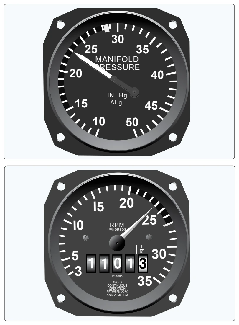
All reciprocating-engine powered aircraft must have a revolutions per minute (rpm) indicator for each engine. Aircraft equipped with a constant-speed propeller or rotor system use a manifold pressure gauge to monitor power output and a tachometer to monitor propeller or rotor speed. Both instruments depict the maximum operating limit with
a red radial line and the normal operating range with a green arc. [Figure 9-4] Some instruments may have a yellow arc to indicate a caution area.
Weight and Loading Distribution
Weight and Loading Distribution contains the maximum certificated weights, as well as the center of gravity (CG) range. The location of the reference datum used in balance computations is included in this section. Weight and balance computations are not provided in this area, but rather in the weight and balance section of the AFM/POH.
Flight Limits
Flight Limits list authorized maneuvers with appropriate entry speeds, flight load factor limits, and types of operation limits. It also indicates those maneuvers that are prohibited, such as spins or acrobatic flight, as well as operational limitations such as flight into known icing conditions.
Placards
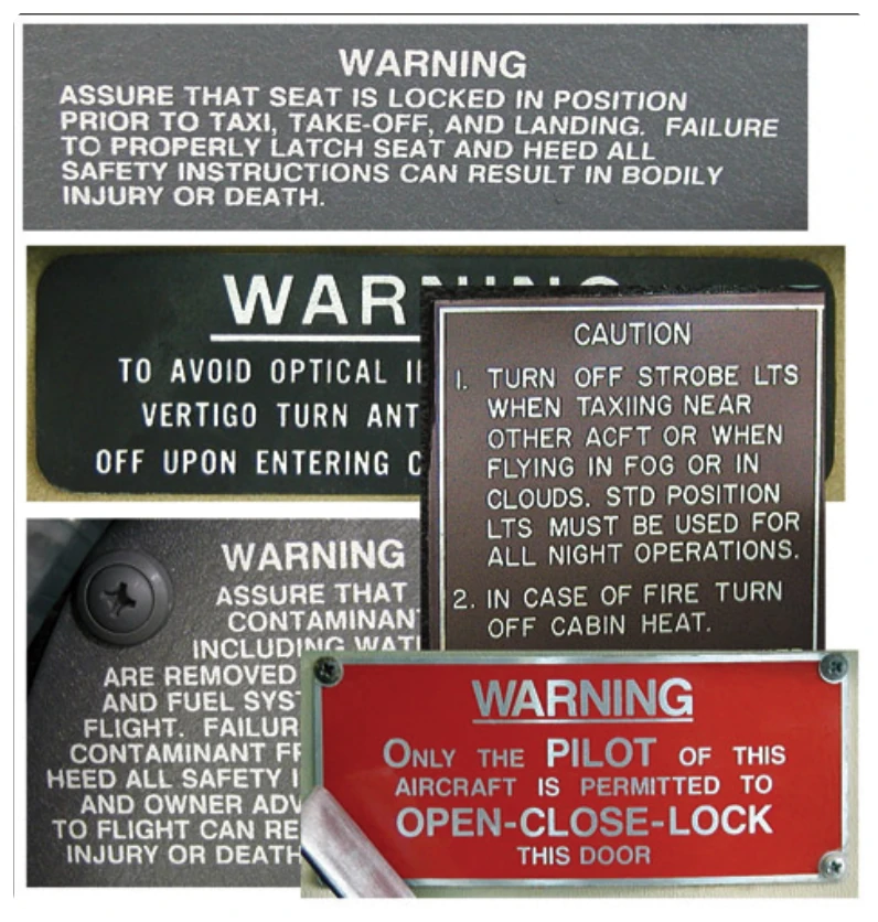
Most aircraft display one or more placards that contain information having a direct bearing on the safe operation of the aircraft. These placards are located in conspicuous places and are reproduced in the Limitations section or as directed by an Airworthiness Directive (AD). [Figure 9-5] Airworthiness Directives are explained in detail later in this chapter.
Emergency Procedures (Section 3)
Checklists describing the recommended procedures and airspeeds for coping with various types of emergencies or critical situations are located in the Emergency Procedures section. Some of the emergencies covered include: engine failure, fire, and system failure. The procedures for inflight engine restarting and ditching may also be included. Manufacturers may first show an emergency checklist in an abbreviated form with the order of items reflecting the sequence of action. Amplified checklists that provide additional information on the procedures follow the abbreviated checklist. To be prepared for emergency situations, memorize the immediate action items and, after completion, refer to the appropriate checklist.
Manufacturers may include an optional subsection entitled Abnormal Procedures. This subsection describes recommended procedures for handling malfunctions that are not considered emergencies.
Normal Procedures (Section 4)
This section begins with a list of the airspeeds for normal operations. The next area consists of several checklists that may include preflight inspection, before starting procedures, starting engine, before taxiing, taxiing, before takeoff, climb, cruise, descent, before landing, balked landing, after landing, and post flight procedures. An Amplified Procedures area follows the checklists to provide more detailed information about the various previously mentioned procedures.