Aviation Training Experts™

handbook

Airplane Flying Handbook

FAA-H-8083-3C Version 2021

Chapter 2

Ground Operations

Introduction

Experienced pilots place a strong emphasis on ground operations as this is where safe flight begins and ends. They know that hasty ground operations diminish their margin of safety. A smart pilot takes advantage of this phase of flight to assess various factors including the regulatory requirements, the pilot’s readiness for pilot-in-command (PIC) responsibilities, the airplane’s condition, the flight environment, and any external pressures that could lead to inadequate control of risk.

Flying an airplane presents many new responsibilities not required for other forms of transportation. Focus is often placed on the flying portion itself with less emphasis placed on ground operations. However pilots need to allow time for flight preparation. Situational awareness begins during preparation and only ends when the airplane is safely and securely returned to its tie-down or hangar, or if a decision is made not to go.

This chapter covers the essential elements for the regulatory basis of flight including:

1. An airplane’s airworthiness requirements,
2. Important inspection items when conducting a preflight visual inspection,
3. Managing risk and resources, and
4. Proper and effective airplane surface movements using the AFM/POH and airplane checklists.

Preflight Assessment of the Aircraft

The visual preflight assessment mitigates airplane flight hazards. The preflight assessment ensures that any aircraft flown meets regulatory airworthiness standards and is in a safe mechanical condition prior to flight. Per 14 CFR part 3, section 3.5(a), the term “airworthy” means that the aircraft conforms to its type design and is in condition for safe operation. The owner/operator is primarily responsible for maintenance, but in accordance with 14 CFR part 91, section 91.7(a) and (b) no person may operate a civil aircraft unless it is in an airworthy condition and the pilot in command of a civil aircraft is responsible for determining whether the aircraft is in condition for safe flight. The pilot's inspection should involve the following:

1. Inspecting the airplane’s airworthiness status.
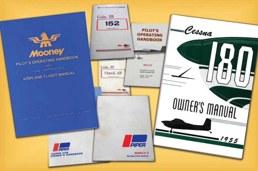
2. Following the AFM/POH to determine the required items for visual inspection. [Figures 2-1, 2-2, 2-3].
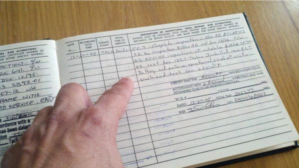
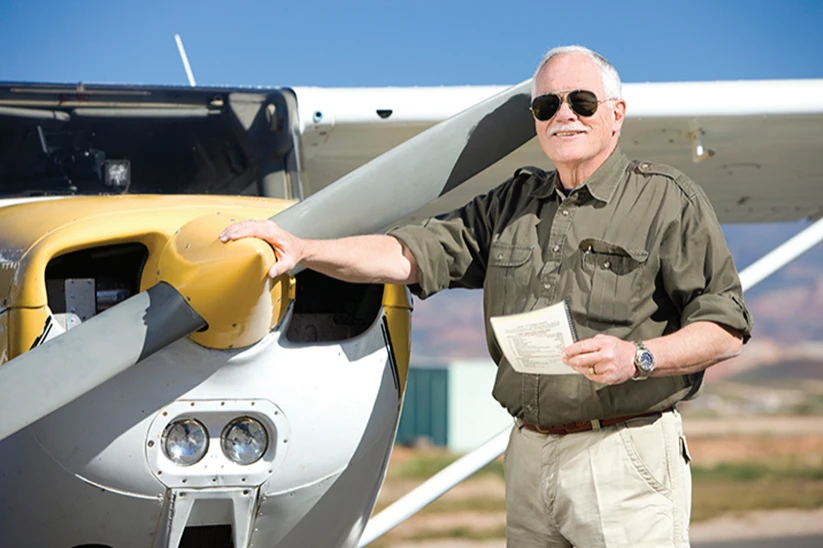
Figure 2-1. Pilots should view the aircraft’s maintenance logbook prior to flight to ensure the aircraft is safe to fly.
Figure 2-2. A visual inspection of the aircraft before flight is an important step in mitigating airplane flight hazards.
Figure 2-3. Airplane Flight Manuals (AFM) and the Pilot Operating Handbook (POH) for each individual aircraft explain the required items for inspection.

Each airplane has a set of logbooks that include airframe and engine, and in some cases, propeller and appliance logbooks, which are used to record maintenance, alteration, and inspections performed on a specific airframe, engine, propeller, or appliance. It is important that the logbooks be kept accurate, secure, and available for inspection. Airplane logbooks are not normally kept in the airplane. It should be a matter of procedure by the pilot to inspect the airplane logbooks or a summary of the airworthy status prior to flight to ensure that the airplane records of maintenance, alteration, and inspections are current and correct. [Figure 2-4] The following is required:

⦁ Annual inspection within the preceding 12 calendar months (Title 14 of the Code of Federal Regulations (14 CFR) part 91, section 91.409(a))
⦁ 100-hour inspection, if the aircraft is operated for hire (14 CFR part 91, section 91.409(b))
⦁ Transponder certification within the preceding 24 calendar months (14 CFR part 91, section 91.413)
⦁ Static system and encoder certification, within the preceding 24 calendar months, required for instrument flight rules (IFR) flight in controlled airspace (14 CFR part 91, section 91.411)
⦁ 30-day VHF omnidirectional range (VOR) equipment check when using the VOR system of radio navigation for IFR flight (14 CFR part 91, section 91.171)
⦁ Emergency locator transmitter (ELT) inspection within the last 12 months (14 CFR part 91, section 91.207(d))
⦁ ELT battery due (14 CFR part 91, section 91.207(c))
⦁ Current status of life limited parts per Type Certificate Data Sheets (TCDS) (14 CFR part 91, section 91.417)
⦁ Status, compliance, logbook entries for airworthiness directives (ADs) (14 CFR part 91, section 91.417(a) (2)(v))
⦁ Federal Aviation Administration (FAA) Form 337, Major Repair or Alteration (14 CFR part 91, section 91.417)
⦁ Inoperative equipment (14 CFR part 91, section 91.213)
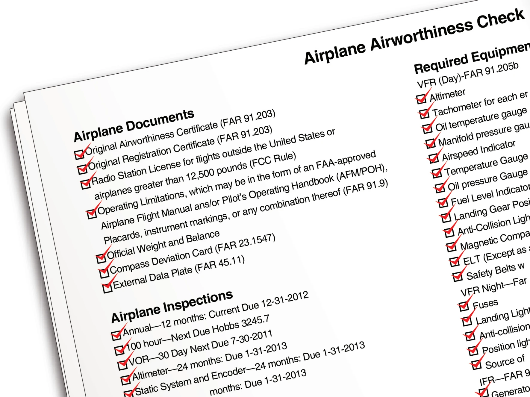
Figure 2-4. A sample airworthiness checklist used by pilots to inspect an aircraft.

A review determines if the required maintenance and inspections have been performed on the airplane. Any discrepancies need to be addressed prior to flight. Once the pilot has determined that the airplane’s logbooks provide factual assurance that the airplane meets its airworthiness requirements, it is appropriate to inspect the airplane visually. The visual preflight inspection of the airplane should begin while approaching the airplane on the ramp. The pilot should make note of the general appearance of the airplane, looking for discrepancies such as misalignment of the landing gear and airplane structure. The pilot should also take note of any distortions of the wings, fuselage, and tail, as well as skin damage and any staining, dripping, or puddles of fuel or oils.

The pilot needs to determine that the following documents are, as appropriate, on board, attached, or affixed to the airplane:

The pilot needs to determine that the following documents are, as appropriate, on board, attached, or affixed to the airplane:

⦁ Current Airworthiness Certificate (14 CFR part 91, section 91.203)
⦁ Current Registration Certificate (14 CFR part 91, section 91.203)
⦁ Radio station license for flights outside the United States or airplanes greater than 12,500 pounds (Federal Communications Commission (FCC) rule)
⦁ Operating limitations, which may be in the form of an FAA-approved AFM/POH, placards, instrument markings, or any combination thereof (14 CFR part 91, section 91.9)
⦁ Current weight and balance data
⦁ Compass correction card, if required under applicable airworthiness standards
⦁ External data plate (14 CFR part 45, section 45.11)

Visual Preflight Assessment

The inspection should start with the cabin door. If the door is hard to open or close, does not fit snugly, or the door latches do not engage or disengage smoothly, the surrounding structure, such as the doorpost, should be inspected for misalignment, which could indicate structural damage. The visual preflight inspection should continue to the interior of the cabin or flight deck where carpeting should be inspected to ensure that it is serviceable, dry, and properly affixed; seat belts and shoulder harnesses should be inspected to ensure that they are free from fraying, latch properly, and are securely attached to their mounting fittings; seats should be inspected to ensure that the seats properly latch into the seat rails through the seat lock pins and that seat rail holes are not abnormally worn to an oval shape; [Figure 2-5] the windshield and windows should be inspected to ensure that they are clean and free from cracks, and crazing. A dirty, scratched, and/or a severely crazed window can result in near zero visibility due to light refraction at certain angles from the sun.

Figure 2-5. Seats should be inspected to ensure that they are properly latched into the seat rails and checked for damage.

The AFM/POH or a third party checklist based on the AFM/POH may be used to conduct the visual preflight inspection, and each manufacturer has a specified sequence for conducting the actions. In general, the following items are likely to be included in the AFM/POH preflight inspection:

⦁ Landing gear control is DOWN, if applicable.
⦁ Master, alternator, and magneto switches are OFF.
⦁ Control column locks are REMOVED.
⦁ Fuel selectors should be checked for proper operation in all positions, including the OFF position. Stiff fuel selectors or where the tank position is not legible or lacking detents are unacceptable.
⦁ Trim wheels, which include elevator and may include rudder and aileron, are set for takeoff position.
⦁ Mechanical air-driven gyro instruments should be inspected for signs of hazing on the instrument face, which may indicate leaks.
⦁ Avionics master is OFF.
⦁ Circuit breakers checked IN.
⦁ Confirm that the landing gear handle is in the DOWN position, then turn the master switch ON. Note the fuel quantities on the fuel gauges and compare to the tank level by visual inspection. If so equipped, fuel pumps may be placed in the ON position to verify fuel pressure in the proper operating range.
⦁ Other items may include checking that lights for both the interior and exterior airplane positions are operating and checking any annunciator panels.
⦁ If the airplane has retractable gear, landing gear down and locked lights are checked green.
⦁ Flight instruments should read as follows:
⦁ Airspeed should read zero.
⦁ The altimeter, when properly set to the current barometric setting, should indicate the field elevation within 75 feet for IFR flight.
⦁ If installed, the magnetic compass should indicate the airplane’s direction accurately; and the compass correction card should be legible and complete. For conventional wet magnetic compasses, the instrument face should be clear and the instrument case full of fluid. A cloudy instrument face, bubbles in the fluid, or a partially filled case renders the compass unusable.
⦁ The vertical speed indictor (VSI) should read zero. If the VSI does not show a zero reading, a small screwdriver can be used to zero this instrument if not part of an electronic display. The mechanical VSI is the only flight instrument that a pilot has the prerogative to adjust. All others need to be adjusted by an FAA-certificated repairman or mechanic.
⦁ Avionics master switch ON to check avionics. Avionics master switch OFF, master switch OFF.

Aircraft equipped with Integrated Flight Deck (IFD) “glass-panel” avionics and supporting systems have specific requirements for checking prior to flight. Ground-based inspections may include verification that the flight deck reference guide is in the aircraft and accessible; checking of system driven removal of “Xs” over engine indicators; checking pitot/static and attitude displays; testing of low level alarms and annunciator panels; setting of fuel levels; and verification that the avionics cooling fans, if equipped, are functional. [Figure 2-6] The AFM/POH specifies how these preflight inspections are to take place. Since an advanced avionics aircraft preflight checklist may be extensive, pilots should allow time to ensure that all items are properly addressed.

Figure 2-6. Ground-based inspections include verification that “Xs” on the instrument display are displayed until the sensor activates.

Outer Wing Surfaces and Tail Section

Generally, the AFM/POH specifies a sequence for the pilot to inspect the aircraft that may sequence from the cabin entry access opening and then in a counterclockwise direction until the aircraft has been completely inspected. Besides the AFM/POH preflight assessment, the pilot should also develop awareness for potential areas of concern, such as signs of deterioration or distortion of the structure, whether metal or composite, as well as loose or missing rivets or screws.

In addition to items specified in the AFM/POH for inspection, the pilot should have an awareness for critical areas, such as spar lines, wing, horizontal, and vertical attach points including wing struts and landing gear attachment areas. The airplane skin should be inspected in these areas as load-related stresses are concentrated along spar lines and attach points. Spar lines are lateral rivet lines that extend across the wing, horizontal stabilizer, or vertical stabilizer. Pilots should pay close attention to spar lines looking for distortion, ripples, bubbles, dents, creases, or waves as any structural deformity may be an indication of internal damage or failure. Inspect around rivet heads looking for cracked paint or a black-oxide film that forms when a rivet works free in its hole. [Figure 2-7]

Figure 2-7. Example of rivet heads where black oxide film has formed due to the rivet becoming loose in its hole.

Additional areas that should be scrutinized are the leading edges of the wing, horizontal stabilizer, and vertical stabilizer. These areas may have been impact-damaged by rocks, ice, birds, and/or hangar rash incidents. Certain dents and dings may render the structure unairworthy. Some leading edge surfaces have aerodynamic devices, such as stall fences, slots, or vortex generators, and deicing equipment, such as weeping wings and boots. If these items exist on the airplane, the pilot should know their proper condition so that an adequate preflight inspection may occur.

On metal airplanes, wingtips, fairings, and non-structural covers may be fabricated out of thin fiberglass or plastic. These items are frequently affected by cracks radiating from screw holes or concentrated radii. Often, if any of these items are cracked, it is practice to “stop-drill” the crack to prevent crack progression. [Figure 2-8] Extra care should be exercised to ensure that these devices are in good condition without cracks that may render them unairworthy. Cracks that have continued beyond a stop-drilled location or any new adjacent cracks that have formed may lead to in-flight failure.

Figure 2-8. Cracks radiating from screw holes that have been stop-drilled to prevent crack progression.

Inspecting composite airplanes can be more challenging as the airplanes generally have no rivets or screws to aid the pilot in identifying spar lines and wing attach points. However, delamination of spar to skin or other structural problems may be identified by bubbles, fine hair-line cracks, or changes in sound when gently tapping on the structure with a fingertip. Anything out of place should be addressed by discussing the issue with a properly rated aircraft mechanic.

Fuel and Oil

While there are various formulations of aviation gasoline (AVGAS), only three grades are conventional: 80/87, 100LL, and 100/130. 100LL is the most widely available in the United States. AVGAS is dyed with a faint color for grade identification: 80/87 is dyed red; 100LL is dyed blue; and 100/130 is dyed green. All AVGAS grades have a familiar gasoline scent and texture. 100LL with its blue dye is sometimes difficult to identify unless a fuel sample is held up against a white background in reasonable white lighting.

Aircraft piston engines certificated for grade 80/87 run satisfactorily on 100LL if approved as an alternate. The reverse is not true. Fuel of a lower grade should never be substituted for a required higher grade. Detonation will severely damage the engine in a very short period of time. Detonation, as the name suggests, is an explosion of the fuel-air mixture inside the cylinder. During detonation, the fuel/air charge (or pockets within the charge) explodes rather than burns smoothly. Because of this explosion, the charge exerts a much higher force on the piston and cylinder, leading to increased noise, vibration, and cylinder head temperatures. The violence of detonation also causes a reduction in power. Mild detonation may increase engine wear, though some engines can operate with mild detonation regularly. However, severe detonation can cause engine failure in minutes. [Figure 2-9] Because of the noise that it makes, detonation is "engine knock" or "pinging" in cars.

When approved for the specific airplane to be flown, automobile gasoline is sometimes used as a substitute fuel in certain airplanes. Its use is acceptable only when the particular airplane has been issued a Supplemental Type Certificate (STC) to both the airframe and engine.

Jet fuel is a kerosene-based fuel for turbine engines and a new generation of diesel-powered airplanes. Jet fuel has a stubborn, distinctive, non-gasoline odor and is oily to the touch. Jet fuel is clear or straw-colored, although it may appear dyed when mixed with AVGAS. Jet fuel has disastrous consequences when introduced into AVGAS-burning reciprocating airplane engines. A reciprocating engine operating on jet fuel may start, run, and power the airplane long enough for the airplane to become airborne, only to have the engine fail catastrophically after takeoff.

Figure 2-9. An aircraft piston showing damage that occurred in just minutes as a result of detonation and overheating.

Jet fuel refueling trucks and dispensing equipment are marked with JET-A placards in white characters on a black background. Because of the dire consequences associated with misfueling, fuel nozzles are specific to the type of fuel. AVGAS fuel filler nozzles are straight with a constant diameter. [Figure 2-10] However, jet fuel filler nozzles are flared at the end to prevent insertion into AVGAS fuel tanks. [Figure 2-11]

Figure 2-10. An AVGAS fuel filler nozzle is straight with a constant diameter.
Figure 2-11. A jet fuel filler nozzle is flared at the end to prevent an inadvertent insertion into an AVGAS tank.

Using the proper, approved grade of fuel is critical for safe, reliable engine operation. Without the proper fuel quantity, grade, and quality, the engine(s) will likely cease to operate. Therefore, it is imperative that the pilot visually verify that the airplane has the correct fuel quantity for the intended flight plus adequate and legal reserves, as well as inspect that the fuel is of the proper grade and that the quality of the fuel is acceptable. The pilot should always ensure that the fuel caps have been securely replaced following each fueling.

Many airplanes experience sensitivity to attitude when fueling for maximum capacity. Nosewheel or main landing gear strut extension, both high as well as low, and the slope of the ramp can significantly alter the attitude of the aircraft and therefore the fuel capacity. Always positively confirm the fuel quantity indicated on the fuel gauges by visually inspecting the level of fuel in each tank.

The pilot should be aware that fuel stains anywhere on the wing or any location where a fuel tank is mounted warrants further investigation—no matter how old the stains appear to be. Fuel stains are a sign of probable fuel leakage. On airplanes equipped with wet-wing fuel tanks, evidence of fuel leakage can be found along rivet lines. [Figure 2-12]

Figure 2-12. Evidence of fuel leakage can be found along rivet lines.

Checking for water and other sediment contamination is a key preflight item. Water tends to accumulate in fuel tanks from condensation, particularly in partially filled tanks. Because water is heavier than fuel, it tends to collect in the low points of the fuel system. Water can also be introduced into the fuel system from deteriorated gas cap seals exposed to rain or from the supplier’s storage tanks and delivery vehicles. Sediment contamination can arise from dust and dirt entering the tanks during refueling or from deteriorating rubber fuel tanks or tank sealant. Deteriorating rubber from seals and sealant may show up in the fuel sample as small dark specks.

The best preventive measure is to minimize the opportunity for water to condense in the tanks. If possible, the fuel tanks should be completely filled with the proper grade of fuel after each flight, or at least filled after the last flight of the day. The more fuel that is in the tanks, the less room there is for condensation to occur. Keeping fuel tanks filled is also the best way to slow the aging of rubber fuel tanks and tank sealant.

Sufficient fuel should be drained from the fuel strainer quick drain and from each fuel tank sump to check for fuel grade/color, water, dirt, and odor. If water is present, it is usually in bubble or bead-like droplets, different in color (usually clear, sometimes muddy yellow to brown with specks of dirt), in the bottom of the sample jar. In extreme water contamination cases, consider the possibility that the entire fuel sample, particularly if a small sample was taken, is water. If water is found in the first fuel sample, continue sampling until no water and contamination appears. Significant and/or consistent water, sediment or contaminations are grounds for further investigation by qualified maintenance personnel. Each fuel tank sump should be drained during preflight and after refueling. The order of sumping the fuel system is often very important. Check the AFM/POH for specific procedures and order to be followed.

Checking the fuel tank vent is an important part of a preflight assessment. If outside air is unable to enter the tank as fuel is drawn into the engine, the eventual result is fuel starvation and engine failure. During the preflight assessment, the pilot should look for signs of vent damage and blockage. Some airplanes utilize vented fuel caps, fuel vent tubes, or recessed areas under the wings where vents are located. The pilot should use a flashlight to look at the fuel vent to ensure that it is free from damage and clear of obstructions. If there is a rush of air when the fuel tank cap is cracked, there could be a serious problem with the vent system.

Aviation oils are available in various single/multi-grades and mineral/synthetic-based formulations. It is important to use the approved and recommended oil for the engine at all times. The oil not only acts as a lubricant but also as a medium to transfer heat as a result of engine operation and to suspend dirt, combustion byproducts, and wear particles between oil changes. Therefore, the proper level of oil is required to ensure lubrication, effective heat transfer, and the suspension of various contaminants. The oil level should be checked during each preflight, rechecked with each refueling, and maintained to prevent the oil level from falling below the minimum required during engine operation.

During the preflight assessment, if the engine is cold, oil levels on the oil dipstick show higher levels than if the engine was warm and recently shutdown after a flight. When removing the oil dipstick, care should be taken to keep the dipstick from coming in contact with dirty or grimy areas. The dipstick should be inspected to verify the oil level. Typically, piston airplane engines have oil reservoirs with capacities between four and eight quarts, with six quarts being common. Aside from the level of oil, the oil’s color also provides an insight as to its operating condition. Oils darken in color as the oil operating hours increase—this is common and expected as the oil traps contaminants. However, oils that rapidly darken in the first few hours of use after an oil change may indicate engine cylinder problems. Piston airplane engines consume a small amount of oil during normal operation. The amount of consumption varies on many factors; however, if consumption increases or suddenly changes, qualified maintenance personnel should investigate

It is suggested that the critical aspect of fuel and oil not be left to line service personnel without oversight of the pilot responsible for flight. While line personnel are aviation professionals, the pilot is responsible for the safe outcome of any flight. During refueling or when oil is added to an engine, the pilot should monitor and ensure that the correct quantity, quality, and grade of fuel and oil is added and that all fuel and oil caps have been securely replaced.

Landing Gear, Tires, and Brakes

The landing gear, tires, and brakes allow the airplane to maneuver from and return to the ramp, taxiway, and runway environment in a precise and controlled manner. The landing gear, tires, and brakes should be inspected to ensure that the airplane can be positively controlled on the ground. Landing gear on airplanes varies from simple fixed gear to complex retractable gear systems.

Fixed landing gear is a gear system in which the landing gear struts, tires, and brakes are exposed and lend themselves to relatively simple inspection. However, more complex airplanes may have retractable landing gear with multiple tires per landing gear strut, landing gear doors, over-center locks, springs, and electrical squat switches. Regardless of the system, the pilot should follow the AFM/POH during inspection to determine that the landing gear is ready for operation.

On many fixed-gear airplanes, inspection of the landing gear system can be hindered by wheel pants, which are covers used to reduce aerodynamic drag. It is still the pilot’s responsibility to inspect the airplane properly. A flashlight helps the pilot in peering into covered areas. On low-wing airplanes, covered or retraceable landing gear presents additional effort required to crouch below the wing to inspect the landing gear properly.

The following provides guidelines for inspecting the landing gear system; however, the AFM/POH should be the pilot’s reference for the appropriate procedures.

⦁ The pilot, when approaching the airplane, should look at the landing gear struts and the adjacent ground for leaking hydraulic fluid that may be coming from struts, hydraulic lines from landing gear retraction pumps, or from the braking system. Landing gear should be relatively free from grease, oil, and fluid without any undue amounts. Any amount of leaking fluid is unacceptable. In addition, an overview of the landing gear provides an opportunity to verify landing gear alignment and height consistency.
⦁ All landing gear shock struts should also be checked to ensure that they are properly inflated, clean, and free from hydraulic fluid and damage. All axles, links, collars, over-center locks, push rods, forks, and fasteners should be inspected to ensure that they are free from cracks, corrosion, and rust, and are in an airworthy condition.
⦁ Tires should be inspected for proper inflation, an acceptable level of remaining tread, and normal wear pattern. Abnormal wear patterns, sidewall cracks, and damage, such as cuts, bulges, imbedded foreign objects, and visible cords, render the tire unairworthy. For airplanes that are flown by more than one pilot, what happened to the tires on previous flights becomes a significant unknown. Therefore, when possible, the airplane should be moved slightly to allow for evaluation of the complete tire circumference.
⦁ Wheel hubs should be inspected to ensure that they are free from cracks, corrosion, and rust, that all fasteners are secure, and that the air valve stem is straight, capped, and in good condition.
⦁ Brakes and brake systems should be checked to ensure that they are free from rust and corrosion and that all fasteners and safety wires are secure. Brake pads should have a proper amount of material remaining and should be secure. All brake lines should be secure, dry, and free of signs of hydraulic leaks, and devoid of abrasions and deep cracking.
⦁ On tricycle gear airplanes, a shimmy damper is used to damp oscillations of the nose gear and should be inspected to ensure that it is securely attached, is free of hydraulic fluid leaks, and is in overall good condition. Some shimmy dampers do not use hydraulic fluid and instead use an elastomeric compound as the dampening medium. Nose gear links, collars, steering rods, and forks should be inspected to ensure the security of fasteners, minimal free play between torque links, crack-free components, and for proper servicing and general condition.
⦁ On some conventional gear airplanes, those airplanes with a tailwheel or skid, the main landing gear may have bungee cords to help in absorbing landing loads and shocks. The bungee cords must be inspected for security and condition.
⦁ Where the landing gear transitions into the airplane’s structure, the pilot should inspect the attachment points and the airplane skin in the adjacent area—the pilot needs to inspect for wrinkled or other damaged skin, loose bolts, and rivets and verify that the area is free from corrosion.

Engine and Propeller

Properly managing the risks associated with flying requires that the pilot of the airplane identify and mitigate any potential hazards prior to flight to prevent, to the furthest extent possible, a hazard becoming a realized risk. The engine and propeller make up the propulsion system of the airplane—failure of this critical system requires a well-trained and competent pilot to respond with significant time constraints to what is likely to become a major emergency.

The pilot needs to ensure that the engine, propeller, and associated systems are functioning properly prior to operation. This starts with an overview of the cowling that surrounds the airplane engine. The pilot should look for loose, worn, missing, or damaged fasteners, rivets, and latches that secure the cowling around the engine and to the airframe. The pilot should be vigilant as fasteners and rivets can be numerous and surround the cowling requiring a visual inspection from above, the sides, and the bottom. Like other areas on the airframe, rivets should be closely inspected for looseness by looking for signs of a black oxide film around the rivet head. The pilot should pay attention to chipped or flaking paint around rivets and other fasteners as this may be a sign of a lack of security. Any cowling security issues need to be referred to a competent and rated airplane maintenance mechanic.

From the cowling, a general inspection of the propeller spinner, if so equipped, should be completed. Not all airplane/propeller combinations have a spinner, so adherence to the AFM/POH checklist is required. Spinners are subjected to great stresses and should be inspected to be free from dents, cracks, corrosion, and in proper alignment. Cracks may not only occur at locations where fasteners are used but also on the rear-facing spinner plate. In conditions where ice or snow may have entered the spinner around the propeller openings, the pilot should inspect the area to ensure that the spinner is internally free from ice. The engine/propeller/spinner is balanced around the crankshaft and a small amount of ice or snow can produce damaging vibrations. Cracks, missing fasteners, or dents result in a spinner that is unairworthy.

The propeller should be checked for blade erosion, nicks, cracks, pitting, corrosion, and security. On controllable pitch propellers, the propeller hub should be checked for oil leaks that tend to stream directionally from the propeller hub toward the tip. On airplanes so equipped, the alternator/generator drive belts should be checked for proper tension and signs of wear.

When inspecting inside the cowling, the pilot should check all surfaces for oil leaks or deterioration of oil and hydraulic lines, and make certain that the oil cap, filter, oil cooler, and drain plug are secure. The pilot should look for signs of fuel dye, which may indicate a fuel leak. Note that both fuel and oil stains may appear on a cowling inner surface. Observation may be difficult without the aid of a flashlight, so even during day operations, a flashlight is handy when peering into the cowling. The pilot should also check for loose or foreign objects inside the cowling, such as bird nests, shop rags, and/or tools. All visible wires and lines should be checked for security and condition. The exhaust system should be checked for white stains caused by exhaust leaks at the cylinder head or cracks in the exhaust stacks. The heat muffs, which provide cabin heating on some airplanes, should also be checked for general condition and signs of cracks or leaks. An isolated area of oxidized darkened paint on the engine may indicate an area experiencing excessive heat. If visible, the condition of the firewall may be checked for integrity.

The air filter should be checked to ensure that it is free from substantial dirt or restrictions, such as bugs, birds, nests, or other causes of airflow restriction. In addition, air filter elements are made from various materials. In all cases, the element should be free from decomposition and properly serviced.

Risk and Resource Management

Ground operations also include the pilot’s assessment of the risk factors that contribute to safety of flight and the pilot’s management of the resources, which may be leveraged to maximize the flight’s successes. The Risk Management Handbook (FAA-H-8083-2) should be reviewed for a comprehensive discussion of this topic. A review of key points follows.

Approximately 85 percent of all aviation accidents have been determined by the National Transportation Safety Board (NTSB) to have been caused by “failure of the pilot to...” As such, a reduction of these failures is the fundamental cornerstone to risk and resource management. The risks involved with flying an airplane are very different from those experienced in daily activities, such as driving to work. Managing risks and resources requires a conscious effort that goes beyond the stick and rudder skills required to pilot the airplane.

Risk Management

Risk management is a formalized structured process for identifying and mitigating hazards and assessing the consequences and benefits of the accepted risk. A hazard is a condition, event, object, or circumstance that could lead to or contribute to an unplanned or undesired event, such as an incident or accident. It is a source of potential danger. Some examples of hazards are:

1. Marginal weather or environmental conditions
2. Lack of pilot qualification, currency, or proficiency for the intended flight.

Identifying the Hazard

Hazard identification is the critical first step of the risk management process. If pilots do not recognize and properly identify a hazard and choose to continue, the consequences of the risk involved is not managed or mitigated. In the previous examples, the hazard identification process results in the following assessment:

⦁ Marginal weather or environmental conditions is an identified hazard because it may result in the pilot having a skill level that is not adequate for managing the weather conditions or requiring airplane performance that is unavailable.
⦁ The lack of pilot training is an identified hazard because the pilot does not have experience to either meet the legal requirements or the minimum necessary skills to safely conduct the flight.

Risk

Risk is the future impact of a hazard that is not controlled or eliminated. It can be viewed as future uncertainty created by the hazard.

⦁ If the weather or environmental conditions are not properly assessed, such as in a case where an airplane may encounter inadvertent instrument conditions, loss of airplane control may result.
⦁ If the pilot’s lack of training is not properly assessed, the pilot may be placed in flight regimes that exceed the pilot’s stick-and-rudder capability.

Risk Assessment

Risk assessment determines the degree of risk and whether the degree of risk is worth the outcome of the planned activity. Once the planned activity is started, the pilot needs to consider whether to continue or not. A pilot should always have viable alternatives available in the event the original flight plan cannot be accomplished. Thus, hazard and risk are the two defining elements of risk management. A hazard can be a real or perceived condition, event, or circumstance that a pilot encounters. Risk assessment is a quantitative value weighted to a task, action, or event. When armed with the predicted risk assessment of an activity, pilots are able to manage and mitigate their risk.

In the example where marginal weather is the identified hazard, it is relatively simple to understand that the consequences of loss of control during any inadvertent encounter with instrument meteorological conditions (IMC) are likely to be severe for a pilot not prepared to fly on an instrument flight plan. A risk assessment for any such pilot in this example would determine that the risk is unacceptable and as a result, mitigation of the risk is required. Proper risk mitigation would require that flight be canceled or delayed until weather conditions were not conducive for inadvertent flight into instrument meteorological conditions.

Risk Identification

Identifying hazards and associated risk is key to preventing risk and accidents. If a pilot fails to search for risk, it is likely that he or she will neither see it nor appreciate it for what it represents. Unfortunately, in aviation, pilots seldom have the opportunity to learn from their small errors in judgment because even small mistakes in aviation are often fatal. In order to identify risk, the use of standard procedures is of great assistance. Several procedures are discussed in detail in the Risk Management Handbook (FAA-H-8083-2).

Risk Mitigation

Risk assessment is only part of the equation. After determining the level of risk, the pilot needs to mitigate the risk. For example, the VFR pilot flying from point A to point B (50 miles) in marginal flight conditions has several ways to reduce risk:

1. Wait for the weather to improve to good VFR conditions.
2. Take a pilot who is more experienced or who is certified as an instrument flight rules (IFR) pilot.
3. Delay the flight.
4. Cancel the flight.
5. Drive.

Resource Management

Familiarity with crew resource management (CRM) and single-pilot resource management (SRM) enables a crew or pilot to manage all available resources effectively and leads to a successful flight. In general aviation, SRM comes into play more often. The focus of SRM is on the single-pilot operation. SRM integrates the following:

⦁ Situational Awareness
⦁ Human Resource Management
⦁ Task Management
⦁ Aeronautical Decision-making (ADM)

Situational Awareness

Situational awareness is the accurate perception of operational and environmental factors that affect the flight. It is a logical analysis based upon the airplane, external support, environment, and the pilot. It is awareness on what is happening in and around the flight.

Human Resource Management

Human resource management requires an effective use of all available resources: human, equipment, and information.

Human resources include the essential personnel routinely working with the pilot to ensure safety of flight. These people include, but are not limited to: weather briefers, flight line personnel, maintenance personnel, crew members, pilots, and air traffic personnel. Pilots need to communicate effectively with these people. This is accomplished by using the key components of the communication process: inquiry, advocacy, and assertion. Pilots should recognize the need to seek enough information from these resources to make a valid decision. After the necessary information has been gathered, the pilot’s decision should be passed on to those concerned, such as air traffic controllers, crewmembers, and passengers. The pilot may have to request assistance from others and be assertive to resolve some situations safely.

Equipment in many of today’s aircraft includes automated flight and navigation systems. These automatic systems, while providing relief from many routine tasks, present a different set of problems for pilots. The automation intended to reduce pilot workload essentially removes the pilot from the process of managing the aircraft, thereby reducing situational awareness and leading to complacency. Information from these systems needs to be continually monitored to ensure proper situational awareness. Pilots should be aware of both equipment capabilities and equipment limitations in order to manage those systems effectively and safely.

Information workloads and automated systems, such as autopilots, need to be properly managed to ensure a safe flight. By planning ahead, a pilot can effectively reduce workload during critical phases of flight and prevent erosion of performance. The pilot who effectively manages his or her workload completes routine tasks as early as possible to preclude the possibility of becoming overloaded and stressed in the later, more critical stages of the flight.

Task Management

Pilots have a limited capacity for information. Once information flow exceeds the pilot’s ability to process the information mentally, any additional information becomes unattended or displaces other tasks and information already being processed. In addition, distraction and fixation impede the ability to process information. For example, if a pilot becomes distracted and fixates on an instrument light failure, the unnecessary focus displaces capability and prevents appreciation of tasks of greater importance.

Aeronautical Decision-Making (ADM)

Flying safely requires the effective integration of three separate sets of skills: stick-and-rudder skills needed to control the airplane; skills related to proficient operation of aircraft systems; and ADM skills. The ADM process addresses all aspects of decision-making in the flight deck and identifies the steps involved in good decision-making. While the ADM process does not eliminate errors, it helps the pilot recognize errors and enables the pilot to manage the error to minimize its effects. These steps are:

1. Identifying personal attitudes hazardous to safe flight;
2. Learning behavior modification techniques;
3. Learning how to recognize and cope with stress;
4. Developing risk assessment skills;
5. Using all resources; and
6. Evaluating the effectiveness of one’s own personal ADM skills.

Ground Operations

The airport ramp can be a complex environment with airport personnel, passengers, trucks, other vehicles, aircraft, and errant people and animals. The pilot is responsible for the operation of the airplane and should operate safely at all times. Ground operations subject the pilot to unique hazards, and mitigating those hazards requires proper planning and good situational awareness in the ground environment. A mitigation tactic involves reviewing the airport diagram prior to operating and having it readily available at all times. Whether departing to or from the ramp, the pilot needs to understand and capably manage the following:

1. Refueling operations
2. Passenger and baggage security and loading
3. Ramp and taxi operations
4. Standard ramp signals

During refueling operations, it is advisable that the pilot remove all passengers from the aircraft and witness the refueling to ensure that the correct fuel and quantity is dispensed into the airplane and that any caps and cowls are properly secured after refueling.

Passengers may have little experience with the open ramp of an airport. The pilot should ensure the safety of the passengers by cautioning them to move on the surface only as directed. If not under the pilot's direct supervision, passengers should have an escort to ensure their safety and ramp security. Baggage loading and security should also be supervised by the pilot. Unsecured baggage or improperly loaded baggage may adversely affect the center of gravity of the aircraft.

Ramp traffic may vary from a deserted open space to a complex environment with heavy corporate or military aircraft. Powerful aircraft may produce exhaust blast or rotor downwash, for example, which could easily cause a light airplane to become uncontrollable. Mitigating these hazards in a light airplane is important to starting off on a safe flight.

Some ramps may be staffed by personnel to assist the pilot in managing a safe departure from the ramp to the taxiway. Figure 2-13 shows standard aircraft taxiing signals, such as those published in the Aeronautical Information Manual (AIM). There are other standard signals, such as those published in Advisory Circular 00-34, as revised, and by the Armed Forces. Furthermore, operation conditions in many areas may call for a modified set of taxi signals. The signals shown in Figure 2-13 represent a minimum number of the most commonly used signals. Whether this set of signals or a modified set is used is not the most important consideration, as long as each flight operational center uses a suitable, agreed-upon set of signals.

Figure 2-13. Standard hand signals used to assist pilots in managing a safe departure from the ramp to the taxiway or runway. Note that at night, the Emergency Stop signal is used for all stop indications .

Engine Starting

Airplane engines vary substantially and specific procedures for engine starting should be accomplished in reference to the approved engine start checklist as detailed in the airplane’s AFM/POH. However, some generally accepted hazard mitigation practices and procedures are outlined in this section.

Prior to engine start, the pilot needs to ensure that the ramp area surrounding the airplane is clear of persons, equipment, and other hazards that could come into contact with the airplane or the propeller. Also, the pilot should check what is behind the airplane prior to engine start as standard practice. A propeller or other engine thrust can accelerate objects to substantial velocities, causing damage to property, and injuring those on the ground. The pilot should mitigate the hazard of debris being blown into persons or property. At all times before engine start, the anti-collision lights should be turned on. For night operations, the position (navigation) lights should also be on. Finally, just prior to starter engagement, the pilot should always call “CLEAR” out of the side window and wait for a response from anyone who may be nearby before engaging the starter.

When activating the starter, the wheel brakes need to be depressed and one hand kept on the throttle to manage the initial starting engine speed. Ensuring that properly operating brakes are engaged prior to starter engagement prevents the airplane from rapidly lunging forward. After engine start, the pilot manipulates the throttle to set the engine revolutions per minute (rpm) to the AFM/POH- prescribed setting. In general, 1,000 rpm is recommended following engine start to allow oil pressure to rise and to minimize undue engine wear due to insufficient lubrication at high rpm. It is important to service an airplane engine with the proper grade of oil for the seasonal conditions and to apply engine preheat when temperatures approach and descend below freezing.

The oil pressure should be monitored after engine start to ensure that pressure is increasing toward the AFM/POH-specified value. The AFM/POH specifies an oil pressure range for the engine. If the limits are not reached and maintained, serious internal engine damage is likely. In most conditions, oil pressure should rise to at least the lower limit within 30 seconds. To prevent damage, the engine should be shut down immediately if the oil pressure does not rise to the AFM/POH values within the required time.

Engine starters are electric motors designed to produce rapid rotation of the engine crankshaft for starting. These electric motors are not designed for continuous duty. Their service life may be drastically shortened during a prolonged or difficult start as an excess buildup of heat can damage internal starter components. Avoid continuous starter operation for periods longer than 30 seconds without a cool down period of at least 30 seconds to 1 minute (some AFM/POH specify longer cool down routines). The smell of burning insulation from a starter may indicate that the recommended cranking time has been exceeded. After repeated unsuccessful start attempts, the pilot should seek advice from a qualified person to determine the cause for the difficulty.

Although quite rare, the starter motor may remain electrically and mechanically engaged after engine start. This can be detected by a continuous and very high current draw on the ammeter. Some airplanes also have a starter engaged warning light specifically for this purpose. The engine should be shut down immediately if this occurs.

The pilot should be attentive for sounds, vibrations, smells, or smoke that are not consistent with normal after-start operational experience. Any concerns should lead to a shutdown and further investigation.

Hand Propping

The procedures for hand propping should always be in accordance with the AFM/POH and performed only by persons who are competent with hand propping procedures. The consequences of the hazards associated with hand propping are serious to fatal.

Historically, when aircraft lacked electrical systems, it was necessary for pilots and ground personnel to “hand prop” an aircraft for starting. Today, most airplanes are equipped with electric starters, and the starter should be working if the airplane is airworthy. If not, a certificated Aviation Maintenance Technician should be called to make a repair. However, vintage airplanes may be encountered, and an airplane manufactured without an electric starter needs to be hand propped. Since a number of these airplanes have been produced, the procedures for hand propping are described in this section.

A few simple precautions help to avoid accidents when hand propping the engine. While touching a propeller, always assume that the ignition is on. The switches that control the magnetos operate on the principle of short-circuiting the current to turn the ignition off. If the switch is faulty, it can be in the “off” position and still permit current to flow in the magneto primary circuit. This condition could allow the engine to start when the switch is off.

Hand propping an aircraft is a hazardous procedure when done perfectly. Not mitigating the hazards associated with hand propping can lead to serious injury and a runaway airplane. A spinning propeller can be lethal should it strike someone. Persons not trained, not competent, or who do not understand how to mitigate the hazards associated with hand propping should never perform this procedure!

Hand propping requires a team of two properly trained people. Both individuals should be familiar with the airplane and hand propping techniques. The first person is responsible for directing the procedure including pulling the propeller blades through. The second person sits in the airplane to ensure that the brakes are set and to exercise controls as directed by the person pulling the propeller. When hand propping occurs, a person unfamiliar with the controls should never occupy the pilot’s seat.

When hand propping is necessary, the ground surface near the propeller should be stable and free of debris. Loose gravel, wet grass, grease, mud, oil, ice, or snow might cause the person pulling the propeller through to slip into the rotating blades as the engine starts. Unless a firm footing is available, relocate the airplane to mitigate this hazardous consequence.

Both participants should discuss the procedure and agree on voice commands and expected actions. To begin the procedure, the fuel system and engine controls (tank selector, primer, pump, throttle, and mixture) are set for normal start. The ignition/magneto switch should be checked to be sure that it is OFF. Then, the descending propeller blade should be rotated so that it assumes a position slightly above the horizontal. The person doing the hand propping should face the descending blade squarely and stand slightly less than one arm’s length from the blade. If a stance too far away were assumed, it would be necessary to lean forward in an unbalanced condition to reach the blade, which may cause the person to fall forward into the rotating blades when the engine starts. Allowing space for the person to be able to step away as the propeller is pulled down, and the engine starts, serves as safeguard in case the brakes fail.

The procedure and commands for hand propping are:

⦁ Person out front says, “FUEL ON, SWITCH OFF, THROTTLE CLOSED, BRAKES SET.”
⦁ Pilot seat occupant, after making sure the fuel is ON, mixture is RICH, magneto switch is OFF, throttle is CLOSED, and brakes are SET, says, “FUEL ON, SWITCH OFF, THROTTLE CLOSED, BRAKES SET.”
⦁ Person out front, after pulling the propeller through to prime the engine says, “BRAKES AND CONTACT.”
⦁ Pilot seat occupant checks the brakes SET and turns the magnetos switch ON, then says, “BRAKES AND CONTACT.”

The words CONTACT (magnetos ON) and SWITCH OFF (magnetos OFF) are used because they are significantly different from each other. Under noisy conditions or high winds, the words CONTACT and SWITCH OFF are less likely to be misunderstood than SWITCH ON and SWITCH OFF.

The propeller is swung by forcing the blade downward rapidly, pushing with the palms of both hands. If the blade is gripped tightly with the fingers, the person’s body may be drawn into the propeller blades should the engine misfire, "kickback," or rotate momentarily in the opposite direction. As the blade is pushed down, the person should step backward, away from the propeller. If the engine does not start, the propeller should not be repositioned for another attempt until it is verified that the magneto switch is turned OFF. Excessive throttle opening after the engine has fired is the principal cause of backfiring during starting. Gradual opening of the throttle, while the engine is cold, reduces the potential for backfiring. Slow, smooth movement of the throttle assures correct engine operation.

Immediately after the engine starts, check the oil pressure indicator. If oil pressure does not show within 30 seconds, stop the engine and determine the trouble. If oil pressure is indicated, adjust the throttle to the aircraft manufacturer’s specified rpm for engine warmup, which is usually between 1,000 to 1,300 rpm.

Most aircraft reciprocating engines are air-cooled and depend on the forward speed of the aircraft to maintain proper cooling. Therefore, particular care is necessary when operating these engines on the ground. During all ground running, operate the engine with the propeller in full low pitch and headed into the wind with the cowling installed to provide the best degree of engine cooling. Closely monitor the engine instruments at all times. Do not close the cowl flaps for engine warm-up, they need to be in the open position while operating on the ground. When warming up the engine, ensure that personnel, ground equipment that may be damaged, or other aircraft are not in the propeller wash.

When removing the wheel chocks or untying the tail after the engine starts, everyone involved should remember that the propeller is nearly invisible. Serious injuries and fatalities have occurred when people who have just started an engine walk or reach into the propeller arc to remove the chocks, reach the cabin, or when moving toward the tail of the airplane. Before the wheel chocks are removed, the throttle should be set to idle and the chocks approached only from the rear of the propeller. One should never approach the wheel chocks from the front or the side.

Taxiing

Taxiing is the controlled movement of the airplane under its own power while on the surface. Since an airplane is moved under its own power between a parking area and the runway, the pilot needs to understand and be proficient in taxi procedures.

A pilot should maintain situational awareness of the ramp, parking areas, taxiways, runway environment, and the persons, equipment and aircraft at all times. Without such awareness, safety may be compromised. Depending on the airport, the parking, ramp, and taxiways may or may not be controlled. As such, it is important that the pilot completely understands the operating environment. At small, rural airports these areas may be desolate with few aircraft and limited hazards; however, as the complexity of the airport increases so does the potential for hazards. Regardless of the complexity, some generally accepted procedures are appropriate.

⦁ The pilot should be familiar with the parking, ramp, and taxi environment. This can be done by having an airport diagram, if available, out and in view at all times. [Figure 2-14]
⦁ Despite having familiarity with the airport, pilots should carefully review their complete taxi plan. For example, a pilot given the same taxi instructions by ATC, starts expecting those same instructions and might not realize that those instructions no longer apply. It only takes missing one instruction or turn to generate an accident. It is a human tendency to follow the same procedure over and over. This expectation bias has occurred to many pilots who did not stop and carefully consider and evaluate their taxi instructions.
⦁ The pilot should be vigilant of the entire area around the airplane to ensure that the airplane clears all obstructions. If, at any time, there is doubt about a safe clearance from an object, the pilot should stop the airplane and check the clearance. It may be necessary to have the airplane towed or physically moved by a ground crew.
⦁ When taxiing, the pilot’s eyes should be looking outside the airplane scanning from side to side while looking both near and far to assess routing and potential conflicts.
⦁ A safe taxiing speed should be maintained. The primary requirements for safe taxiing are positive control, the ability to recognize any potential hazards in time to avoid them, and the ability to stop or turn where and when desired, without undue reliance on the brakes. Pilots should proceed at a cautious speed on congested or busy ramps. Normally, the speed should be at the rate where movement of the airplane is dependent on the throttle. That is, slow enough so when the throttle is closed, the airplane can be stopped promptly.
⦁ The pilot should place the aircraft on the taxiway center. Some taxiways have above-ground taxi lights and signage that could impact the airplane or propellers if the pilot does not exercise accurate control. When yellow taxiway centerline stripes are present, the pilot should visually place the centerline stripe so it is under the center of the airplane fuselage.
⦁ When taxiing, the pilot should slow down before attempting a turn. Sharp high-speed turns place undesirable side loads on the landing gear and may result in tire damage or an uncontrollable swerve or a ground loop. Swerves are most likely to occur when turning from a downwind heading toward an upwind heading. In moderate to high-wind conditions, the airplane may weathervane increasing the swerving tendency.

Figure 2-14. Airport Diagram of Monterey Peninsula (MRY), Monterey, California.

Steering is accomplished with rudder pedals and brakes. To turn the airplane on the ground, the pilot should apply the rudder in the desired direction of turn and use the appropriate power or brake to control the taxi speed. The rudder pedal should be held in the direction of the turn until just short of the point where the turn is to be stopped. Rudder pressure is then released or opposite pressure is applied as needed.

More engine power may be required to start the airplane moving forward, or to start a turn, than is required to keep it moving in any given direction. When using additional power, the throttle should immediately be retarded once the airplane begins moving to prevent excessive acceleration.

The brakes should be tested for proper operation as soon as the airplane is put in motion. Applying power to start the airplane moving forward slowly, then retarding the throttle and simultaneously applying just enough pressure to one side, then the other to confirm proper function and reaction of both brakes. This is best if the airplane has individual left/right brakes to stop the airplane. If braking performance is unsatisfactory, the engine should be shut down immediately.

When taxiing at appropriate speeds in no-wind conditions, the aileron and elevator control surfaces have little or no effect on directional control of the airplane. These controls should not be considered steering devices and should be held in a neutral position.

When taxiing with a quartering headwind, the wing on the upwind side (the side that the wind is coming from) tends to be lifted by the wind unless the aileron control is held in that direction (upwind aileron UP). Moving the aileron into the UP position reduces the effect of the wind striking that wing, thus reducing the lifting action. This control movement also causes the downwind aileron to be placed in the DOWN position, thus a small amount of lift and drag on the downwind wing, further reducing the tendency of the upwind wing to rise. [Figure 2-15]

When taxiing with a quartering tailwind, the elevator should be held in the DOWN position, and the upwind aileron, DOWN. Since the wind is striking the airplane from behind, these control positions reduce the tendency of the wind to get under the tail and the wing and to nose the airplane over. The application of these crosswind taxi corrections helps to minimize the weathervaning tendency and ultimately results in easier steering. [Figure 2-15]

The presence of moderate to strong headwinds and/or a strong propeller slipstream creates lift on the horizontal tail surfaces and makes it necessary to control the pitch attitude while taxiing. The elevator control in nosewheel-type airplanes should be held in the neutral position, while in tailwheel-type airplanes, it should be held in the full aft position to hold the tail down unless the headwind gets very strong, which allows for an elevator position closer to neutral.

Downwind taxiing usually requires less engine power after the initial ground roll has begun, since the wind is pushing the airplane forward. To avoid overheating the brakes and controlling the airplane’s speed when taxiing downwind, the pilot should keep engine power to a minimum. Rather than continuously riding the brakes to control speed, it is appropriate to apply brakes only occasionally. Other than sharp turns at low speed, the throttle should always be at idle before the brakes are applied. It is a common error to taxi with a power setting that requires controlling taxi speed with the brakes.

Figure 2-15. Control positions of the nosewheel airplane.

Normally, all turns should be started using the rudder pedal to steer the nosewheel. To tighten the turn after full pedal deflection is reached, the brake may be applied as needed. When stopping the airplane, it is always advisable to stop with the nosewheel straight ahead to relieve any side load on the nosewheel and to make it easier to start moving ahead. Note that certain makes and models have no nosewheel steering and the brakes need to be used to control any turns.

During crosswind taxiing, even the nosewheel-type airplane has some tendency to weathervane. However, the weathervaning tendency is less than in tailwheel-type airplanes because the main wheels are located behind the airplane’s center of gravity, and the nosewheel’s ground friction helps to resist the tendency. The nosewheel linkage from the rudder pedals provides adequate steering control for safe and efficient ground handling, and normally, only rudder pressure is necessary to correct for a crosswind.

Taxiing checklists are sometimes specified by the AFM/POH, and the pilot should accomplish any items that are required. If there are no specific checklist items, taxiing still provides an opportunity to verify the operation and cross-check of the flight instruments. In general, the flight instruments should indicate properly with the airspeed at or near zero (depending on taxi speed, wind speed and direction, and lower limit sensitivity); the attitude indicator should indicate pitch and roll level (depending on airplane attitude) with no flags; the altimeter should indicate the proper elevation within prescribed limits; the turn indicator should show the correct direction of turn with the ball movement toward the outside of the turn with no flags; the directional gyro should be set and crossed checked to the magnetic compass and verified accurate to the direction of taxi; and the vertical speed indicator (VSI) should read zero. These checks can be accomplished on conventional mechanical instrumented aircraft or those with glass displays.

Before-Takeoff Check

The before-takeoff check is the systematic AFM/POH procedure for checking the engine, controls, systems, instruments, and avionics prior to flight. Normally, the before-takeoff checklist is performed after taxiing to a run-up position near the takeoff end of the runway. Many engines require that the oil temperature reach a minimum value as stated in the AFM/POH before takeoff power is applied. Taxiing to the run-up position usually allows sufficient time for the engine to warm up to at least minimum operating temperature; however, the pilot should verify that the oil temperature is within the proper range prior to the application of high power.

A suitable location for run-up should be firm (a smooth, paved or turf surface if possible) and free of debris. Otherwise, the propeller may pick up pebbles, dirt, mud, sand, or other loose objects and hurl them backwards. This damages the propeller and may damage the tail of the airplane. Small chips in the leading edge of the propeller form stress risers or high stress concentrations. These are highly undesirable and may lead to cracks and possible propeller blade failure. The airplane should also be positioned clear of other aircraft and the taxiway. There should not be anything behind the airplane that might be damaged by the propeller airflow blasting rearward.

Before beginning the before-takeoff check, after the airplane is properly positioned for the run-up, it should be allowed to roll forward slightly to ensure that the nosewheel or tailwheel is in alignment with the longitudinal axis of the airplane.

While performing the before-takeoff check in accordance with the airplane’s AFM/POH, the pilot divides attention between the inside and outside of the airplane. If the parking brake slips, or if application of the toe brakes is inadequate for the amount of power applied, the airplane could rapidly move forward and go unnoticed if pilot attention is fixed only inside the airplane. A good operational practice is to split attention from one item inside to a look outside.

Air-cooled engines generally are tightly cowled and equipped with baffles that direct the flow of air to the engine in sufficient volumes for cooling while in flight; however, on the ground, much less air is forced through the cowling and around the baffling. Prolonged ground operations may cause cylinder overheating long before there is an indication of rising oil temperature. To minimize overheating during engine run-up, it is recommended that the airplane be headed as nearly as possible into the wind and, if equipped, engine instruments that indicate cylinder head temperatures should be monitored. Cowl flaps, if available, should be set according to the AFM/POH.

Each airplane has different features and equipment and the before-takeoff checklist provided in airplane’s AFM/POH should be used to perform the run-up. Many critical systems are checked and set during the before-takeoff check. Most airplanes have at least the following systems checked and set:

⦁ Fuel System—set per the AFM/POH and verified ON and the proper and correct fuel tanks selected.
⦁ Trim—set for takeoff position, which includes the elevator and may also include rudder and aileron trim.
⦁ Flight Controls—checked throughout their entire operating range. This includes full aileron, elevator, and rudder deflection in all directions. Often, pilots do not exercise a full range of movement of the flight controls, which is not acceptable.
⦁ Engine Operation—checked to ensure that temperatures and pressures are in their normal ranges; magneto or Full Authority Digital Engine Control (FADEC) operation on single or dual ignition are acceptable and within limits; and, if equipped, carburetor heat is functioning. If the airplane is equipped with a constant speed or feathering propeller, that its operation is acceptable, and the engine continues to run normally as the propeller is exercised.
⦁ Electrical System—verified to ensure voltages are within operating range and that the system shows the battery system charging.
⦁ Vacuum System—shows an acceptable level of vacuum, which is typically between 4.8 and 5.2 inches of mercury ("Hg) at 2,000 rpm. Refer to the AFM/POH for the manufacturer’s values. It is important to ensure that mechanical gyroscopic instruments have adequate time to spool up to acceptable rpm in order for them to indicate properly. A hasty and quick taxi and run-up does not allow mechanical gyroscopic instruments to indicate properly and a departure into instrument meteorological conditions (IMC) is unadvisable.
⦁ Flight Instruments–rechecked and set for the departure. Verify that the directional gyro and the magnetic compass are in agreement. If the directional gyro has a heading bug, it may be set to the runway heading that is in use or as assigned by air traffic control (ATC).
⦁ Avionics–set with the appropriate frequencies, initial navigation sources and courses, autopilot preselects, transponder codes, and other settings and configurations based on the airplane’s equipment and flight requirements.
⦁ Takeoff Briefing–made out loud by the pilot even when no other person is there to listen. It should include a visual verification of the correct surface and direction to preclude a wrong surface departure. A sample takeoff briefing may be the following:

Takeoff Checks

The pilot should ensure that runway numbers on paved runways agree with magnetic compass and heading indicators before beginning takeoff roll. The last check as power is brought to full takeoff power includes:

1. Doors latched and windows closed as required?
2. Controls positioned to account for any crosswind?
3. Power correct?
4. Engine rpm normal?
5. Engine smooth?
6. Engine instruments normal and in green ranges?

After-Landing

During the after-landing roll, while maintaining airplane track over runway centerline with ailerons and heading down runway with rudder pedals, the airplane should be gradually slowed to normal taxi speed with normal brake pressure before turning off of the landing runway. Any significant degree of turn at faster speeds could result in subsequent damage to the landing gear, tires, brakes, or the airplane structure.

To give full attention to controlling the airplane during the landing roll, the after-landing checklist should be performed only after the airplane is brought to a complete stop beyond the runway holding position markings. There have been many cases where a pilot has mistakenly manipulated the wrong handle and retracted the landing gear, instead of the flaps, due to improper division of attention while the airplane was moving. However, this procedure may be modified if the manufacturer recommends that specific after-landing items be accomplished during landing rollout. For example, when performing a short-field landing, the manufacturer may recommend retracting the flaps on rollout to improve braking. In this situation, the pilot should make a positive identification of the flap control handle before retracting the flaps.

Clear of Runway and Stopped

Because of different configurations and equipment in various airplanes, the after-landing checklist within the AFM/POH should be used. Some of the items may include:

1. Power—set to the AFM/POH values such as throttle 1,000 rpm, propeller full forward, mixture leaned.
2. Fuel—may require switching tanks and fuel pumps switched off.
3. Flaps—set to the retracted position.
4. Cowl flaps—may be opened or closed depending on temperature conditions.
5. Trim—reset to neutral or takeoff position.
6. Lights—may be switched off if not needed, such as strobe lights.
7. Avionics—frequencies and transponder set for arrival airport taxi procedures.

Parking

Unless parking in a designated, supervised area, the pilot should select a location and heading that prevents propeller or jet blast of other airplanes from striking the airplane unnecessarily. Whenever possible, the airplane should be parked headed into the existing or forecast wind. Often airports have airplane tie downs located on ramp areas which may or may not be aligned with the wind or provide a significant choice in parking location. After stopping in the desired direction, the airplane should be allowed to roll straight ahead enough to straighten the nosewheel or tailwheel.

Engine Shutdown

The pilot should always use the procedures in the airplane’s AFM/POH shutdown checklist for shutting down the engine and securing the airplane. Important items may include:

1. Parking Brake—set to ON.
2. Throttle—set to IDLE or 1,000 rpm.
3. If turbocharged, observe the manufacturer’s spool down procedure.
4. Magneto Switch Test—momentarily check for proper grounding in the OFF position at idle rpm.
5. Propeller Control—set to HIGH rpm, if equipped.
6. Avionics—turn OFF.
7. Alternator—turn OFF.
8. Mixture—set to IDLE CUTOFF.
9. Magneto Switch—turn ignition switch to OFF when engine stops.
10. Install chocks (release parking brake in accordance with AFM/POH).
11. Master Switch—turn OFF.
12. Secure—install control locks and anti-theft security locks.

Post-Flight

A flight is not complete until the engine is shut down and the airplane is secured. A pilot should consider this an essential part of any flight.

Securing and Servicing

After engine shutdown and deplaning passengers, the pilot should accomplish a post-flight inspection. This includes a walk around to inspect the general condition of the aircraft. Inspect near and around the cowling for signs of oil or fuel streaks and around the oil breather for excessive oil discharge. Inspect under wings and other fuel tank locations for fuel stains. Inspect landing gear and tires for damage and brakes for any leaking hydraulic fluid. Inspect cowling inlets for obstructions.

Oil levels should be checked and quantities brought to AFM/POH levels. Fuel should be added based on the immediate use of the airplane. If the airplane is going to be inactive, it is a good operating practice to fill the fuel tanks to prevent water condensation from forming inside the tank. If another flight is planned, the fuel tanks should be filled based on the flight planning requirements for that flight.

The aircraft should be hangared or tied down, flight controls secured, and security locks in place. The type of tie downs may vary significantly from chains to well-worn ropes. Chains are not flexible and as such should not be made taut so as to allow the airplane some movement and prevent airframe structural damage. Tie down ropes are flexible and may be reasonably cinched to the airplane’s tie down rings. Consider utilizing pitot tube covers, cowling inlet covers, rudder gust locks, window sunscreens, and propeller security locks to further enhance the safety and security of the airplane.

Hangaring is not without hazards to the airplane. The pilot should ensure that enough space is allocated to the airplane so it is free from any impact to the hangar, another aircraft, or vehicle. The airplane should be inspected after hangaring to ensure that no damage was imparted on the airplane.

Chapter Summary

This chapter places emphasis on determining the airworthiness of the airplane, preflight visual inspection, managing risk and pilot- available resources, safe surface-based operations, and the adherence to and proper use of the AFM/POH and checklists. The pilot should ensure that the airplane is in a safe condition for flight, and it meets all the regulatory requirements of 14 CFR part 91. A pilot also needs to recognize that flight safety includes proper flight preparation and having the experience to manage the risks associated with the expected conditions. An effective and continuous assessment and mitigation of the risks and appropriate utilization of resources goes a long way provided the pilot honestly evaluates their ability to act as PIC.