Chapter 12
Hydraulic & Pneumatic Power Systems
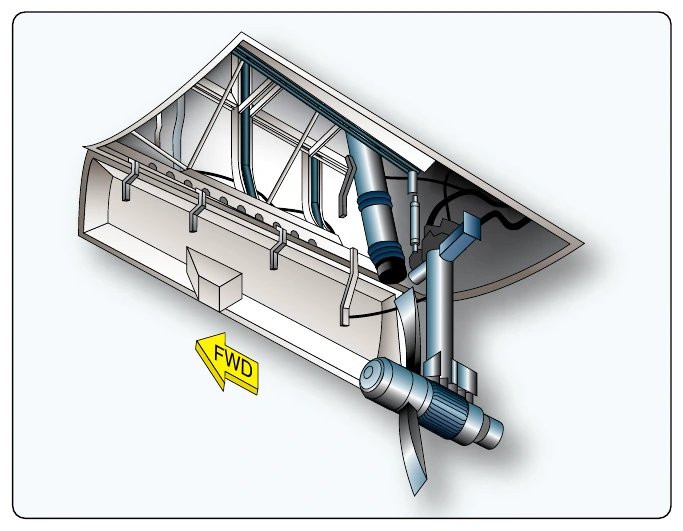
The RAT is installed in the aircraft to provide electrical and hydraulic power if the primary sources of aircraft power are lost. Ram air is used to turn the blades of a turbine that, in turn, operates a hydraulic pump and generator. The turbine and pump assembly is generally installed on the inner surface of a door installed in the fuselage. The door is hinged, allowing the assembly to be extended into the slipstream by pulling a manual release in the flight deck. In some aircraft, the RAT automatically deploys when the main hydraulic pressure system fails, and/or electrical system malfunction occurs. [Figure 12-56]
Power Transfer Unit (PTU)
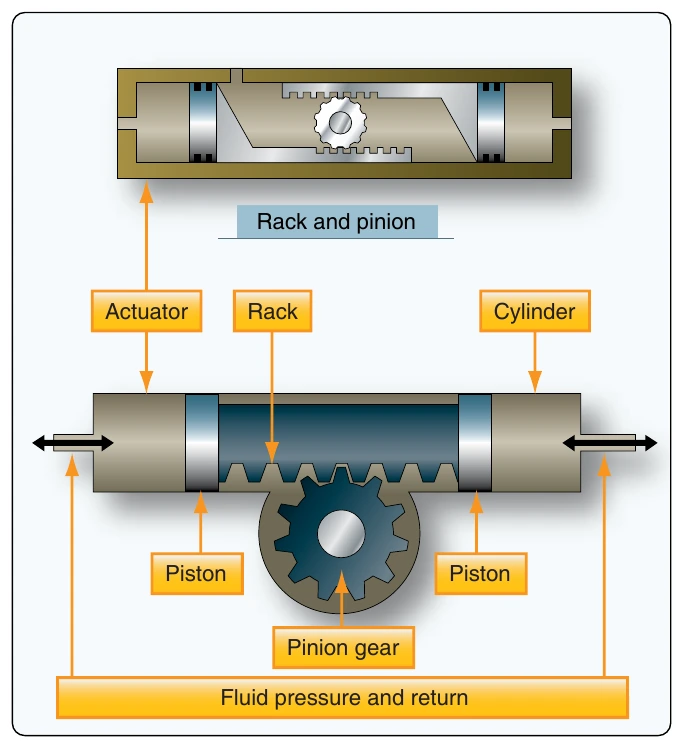
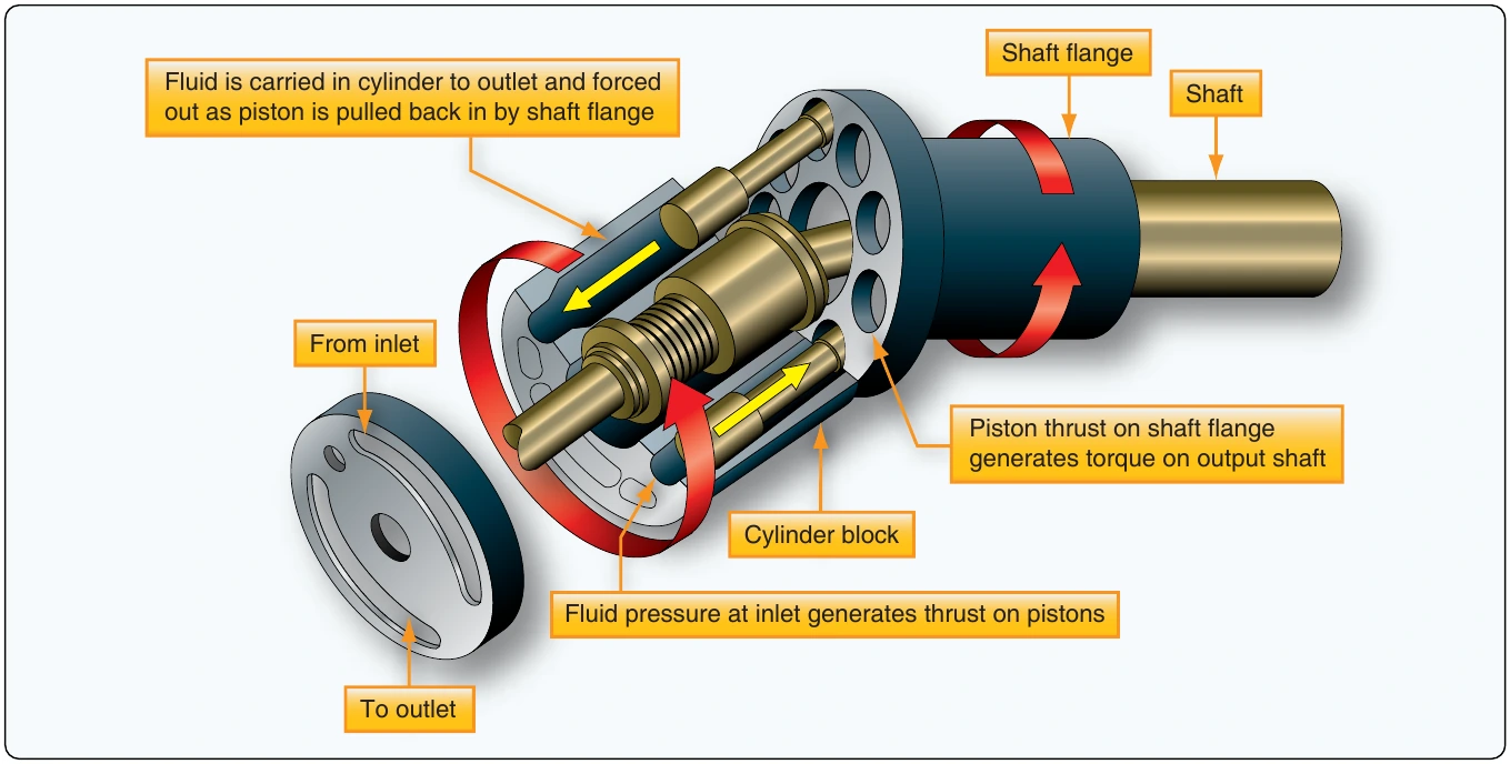
The PTU is able to transfer power but not fluid. It transfers power between two hydraulic systems. Different types of PTUs are in use; some can only transfer power in one direction while others can transfer power both ways. Some PTUs have a fixed displacement, while others use a variable displacement hydraulic pump. The two units, hydraulic pump and hydraulic motor, are connected via a single drive shaft so that power can be transferred between the two systems. Depending on the direction of power transfer, each unit in turn works either as a motor or a pump. [Figure 12-57]
Hydraulic Motor-Driven Generator (HMDG)
The HMDG is a servo-controlled variable displacement motor integrated with an AC generator. The HMDG is designed to maintain a desired output frequency of 400 Hz. In case of an electrical failure, the HMDG could provide an alternative source of electrical power.
Seals
Seals are used to prevent fluid from passing a certain point, and to keep air and dirt out of the system in which they are used. The increased use of hydraulics and pneumatics in aircraft systems has created a need for packings and gaskets of varying characteristics and design to meet the many variations of operating speeds and temperatures to which they are subjected. No one style or type of seal is satisfactory for all installations. Some of the reasons for this are:
- Pressure at which the system operates.
- The type fluid used in the system.
- The metal finish and the clearance between adjacent parts.
- The type motion (rotary or reciprocating), if any.
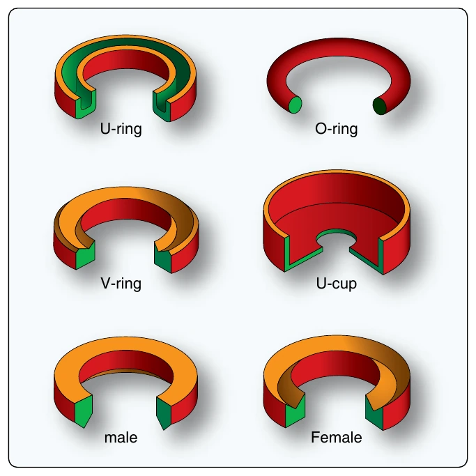
Seals are divided into three main classes: packings, gaskets, and wipers. A seal may consist of more than one component, such as an O-ring and a backup ring, or possibly an O-ring and two backup rings. Hydraulic seals used internally on a sliding or moving assembly are normally called packings. [Figure 12-58] Hydraulic seals used between nonmoving fittings and bosses are normally called gaskets.
V-Ring Packings
V-ring packings (AN6225) are one-way seals and are always installed with the open end of the V facing the pressure. V-ring packings must have a male and female adapter to hold them in the proper position after installation. It is also necessary to torque the seal retainer to the value specified by the manufacturer of the component being serviced, or the seal may not give satisfactory service.
U-Ring
U-ring packings (AN6226) and U-cup packings are used in brake assemblies and brake master cylinders. The U-ring and U-cup seals pressure in only one direction; therefore, the lip of the packings must face toward the pressure. U-ring packings are primarily low-pressure packings to be used with pressures of less than 1,000 psi.
O-Rings
Most packings and gaskets used in aircraft are manufactured in the form of O-rings. An O-ring is circular in shape, The cross-section is truly round and has been molded and trimmed to extremely close tolerances. The O-ring packing seals effectively in both directions. This sealing is done by distortion of its elastic compound.