Chapter 9
Aircraft Electrical System
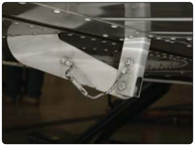
- Bonding connections—to ensure a low-resistance connection, nonconducting finishes, such as paint and anodizing films, should be removed from the attachment surface to be contacted by the bonding terminal. Electrical wiring should not be grounded directly to magnesium parts.
- Corrosion protection—one of the more frequent causes of failures in electrical system bonding and grounding is corrosion. The areas around completed connections should be post-finished quickly with a suitable finish coating.
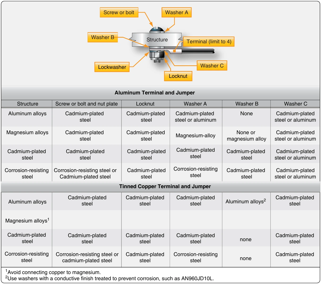
- Corrosion prevention—electrolytic action may rapidly corrode a bonding connection if suitable precautions are not taken. Aluminum alloy jumpers are recommended for most cases; however, copper jumpers should be used to bond together parts made of stainless steel, cadmium-plated steel, copper, brass, or bronze. Where contact between dissimilar metals cannot be avoided, the choice of jumper and hardware should be such that corrosion is minimized; the part likely to corrode should be the jumper or associated hardware.
- Bonding jumper attachment—the use of solder to attach bonding jumpers should be avoided. Tubular members should be bonded by means of clamps to which the jumper is attached. Proper choice of clamp material should minimize the probability of corrosion.
- Ground return connection—when bonding jumpers carry substantial ground return current, the current rating of the jumper should be determined to be adequate, and a negligible voltage drop is produced. [Figure 9-146]
Lacing & Tying Wire Bundles
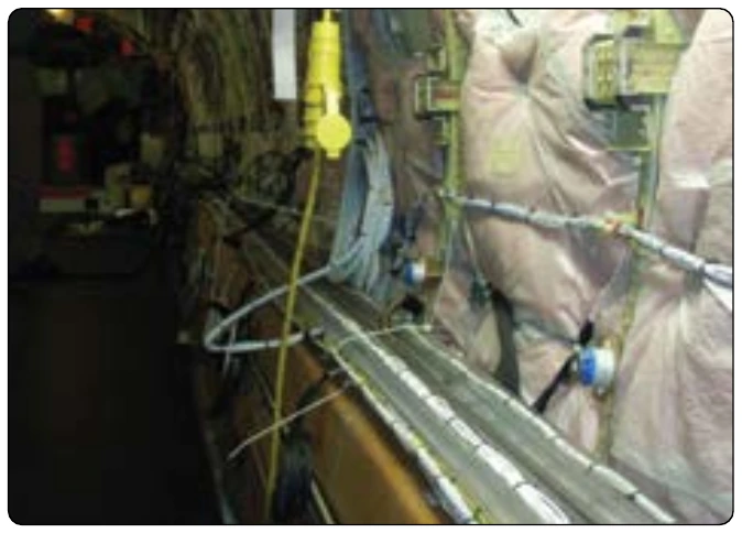
Ties, lacing, and straps are used to secure wire groups or bundles to provide ease of maintenance, inspection, and installation. Straps may not be used in areas of SWAMP, such as wheel wells, near wing flaps, or wing folds. They may not be used in high vibration areas where failure of the strap would permit wiring to move against parts that could damage the insulation and foul mechanical linkages or other moving mechanical parts. They also may not be used where they could be exposed to UV light, unless the straps are resistant to such exposure. [Figure 9-147]
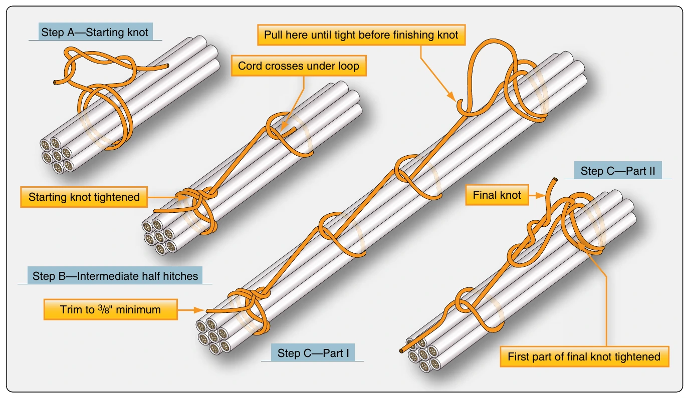
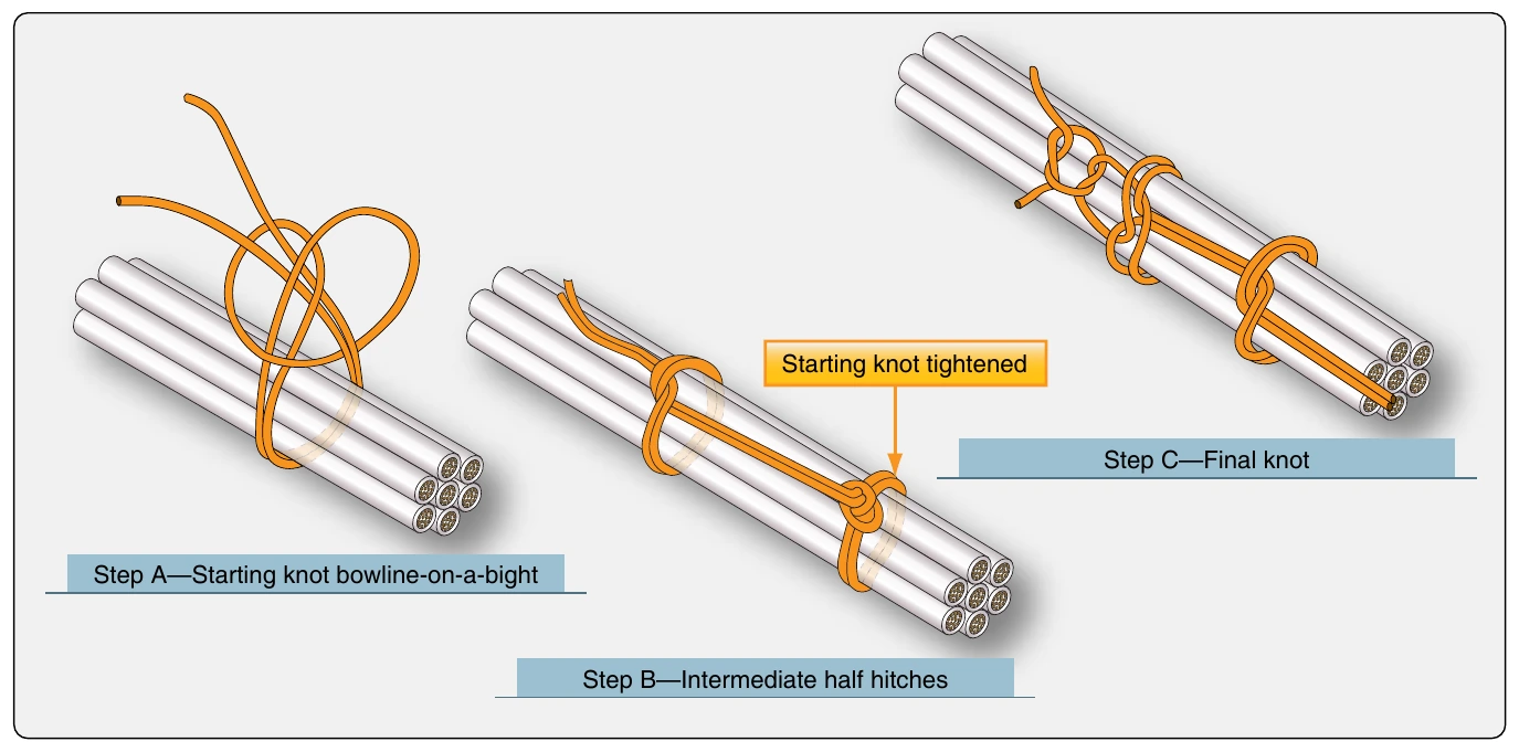
The single cord-lacing method and tying tape may be used for wire groups of bundles 1 inch in diameter or less. The recommended knot for starting the single cord-lacing method is a clove hitch secured by a double-looped overhand knot. [Figure 9-148, step A] Use the double cord-lacing method on wire bundles 1 inch in diameter or larger. When using the double cord-lacing method, employ a bowline-on-a-bight as the starting knot. [Figure 9-149, step A]
Tying
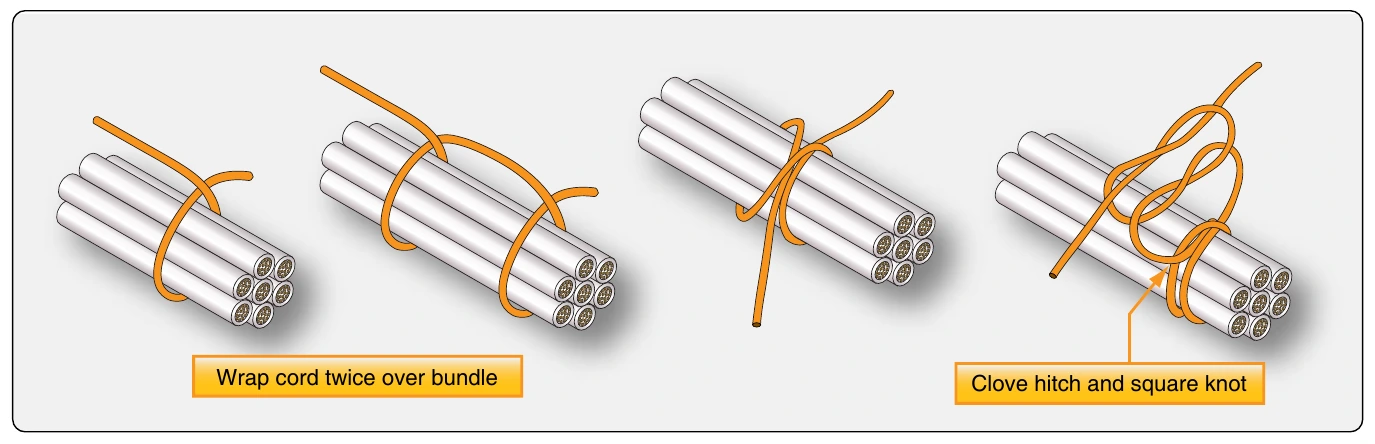
Use wire group or bundle ties where the supports for the wire are more than 12 inches apart. A tie consists of a clove hitch around the wire group or bundle, secured by a square knot. [Figure 9-150]
Wire Termination
Stripping Wire
Before wire can be assembled to connectors, terminals, splices, etc., the insulation must be stripped from connecting ends to expose the bare conductor. Copper wire can be stripped in a number of ways depending on the size and insulation.
Aluminum wire must be stripped using extreme care, since individual strands break very easily after being nicked. The following general precautions are recommended when stripping any type of wire:
- When using any type of wire stripper, hold the wire so that it is perpendicular to cutting blades.
- Adjust automatic stripping tools carefully; follow the manufacturer’s instructions to avoid nicking, cutting, or otherwise damaging strands. This is especially important for aluminum wires and for copper wires smaller than No. 10. Examine stripped wires for damage. Cut off and restrip (if length is sufficient), or reject and replace any wires having more than the allowable number of nicked or broken strands listed in the manufacturer’s instructions.
- Make sure insulation is clean-cut with no frayed or ragged edges. Trim, if necessary.
- Make sure all insulation is removed from stripped area. Some types of wire are supplied with a transparent layer of insulation between the conductor and the primary insulation. If this is present, remove it.
- When using hand-plier strippers to remove lengths of insulation longer than 3⁄4 inch, it is easier to accomplish in two or more operations.
- Retwist copper strands by hand or with pliers, if necessary, to restore natural lay and tightness of strands.
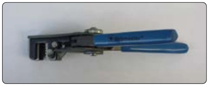
A pair of handheld wire strippers is shown in Figure 9-151. This tool is commonly used to strip most types of wire. The following general procedures describe the steps for stripping wire with a hand stripper.
- Insert wire into exact center of correct cutting slot for wire size to be stripped. Each slot is marked with wire size.
- Close handles together as far as they will go.
- Release handles, allowing wire holder to return to the open position.
- Remove stripped wire.