
Chapter 10
Inspection Concepts & Techniques
Radiation produces change in all matter that it passes through. This is also true of living tissue. When radiation strikes the molecules of the body, the effect may be no more than to dislodge a few electrons, but an excess of these changes could cause irreparable harm. When a complex organism is exposed to radiation, the degree of damage, if any, depends on the body cells that have been changed.
Vital organs in the center of the body that are penetrated by radiation are likely to be harmed the most. The skin usually absorbs most of the radiation and reacts earliest to radiation.
If the whole body is exposed to a very large dose of radiation, death could result. In general, the type and severity of the pathological effects of radiation depend on the amount of radiation received at one time and the percentage of the total body exposed. Smaller doses of radiation could cause blood and intestinal disorders in a short period of time. The more delayed effects are leukemia and other cancers. Skin damage and loss of hair are also possible results of exposure to radiation.
Inspection of Composites
Composite structures are inspected for delamination (separation of the various plies), debonding of the skin from the core, and evidence of moisture and corrosion. Previously discussed methods including ultrasonic, acoustic emission, and radiographic inspections may be used as recommended by the aircraft manufacturer. The simplest method used in testing composite structures is the tap test. Newer methods, such as thermography, have been developed to inspect composite structures.
Tap Testing
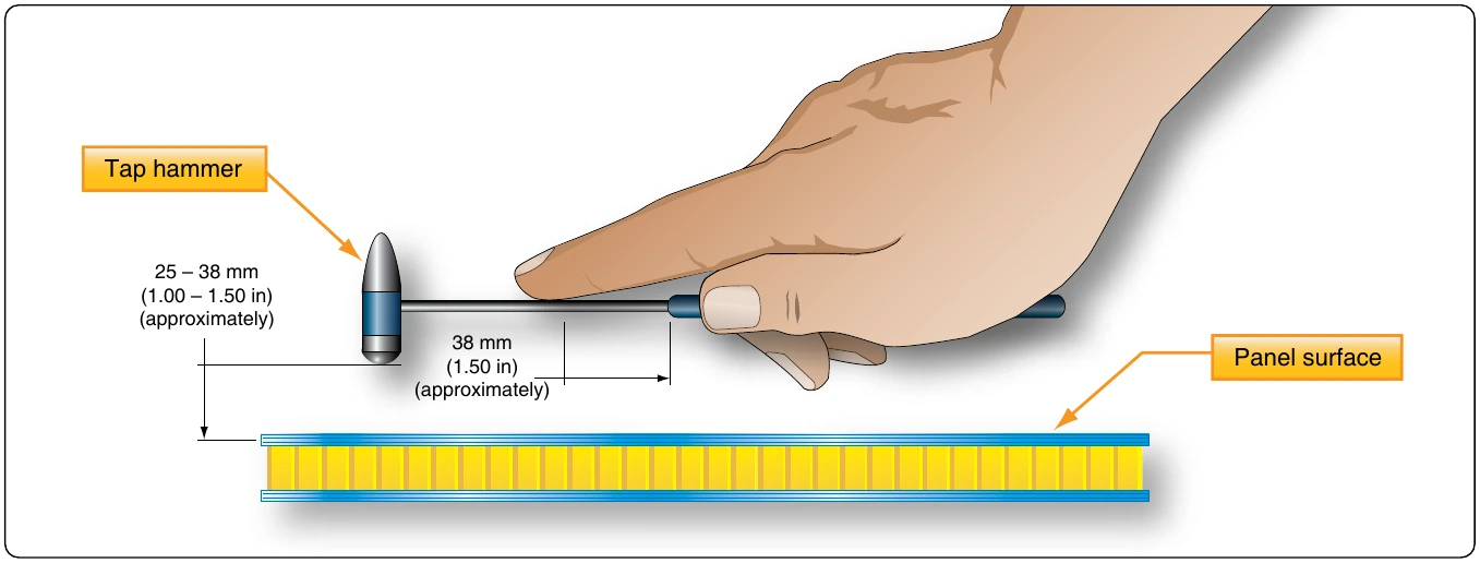
Tap testing, also referred to as the ring test or coin test, is widely used as a quick evaluation of any accessible surface to detect the presence of delamination or debonding. The testing procedure consists of lightly tapping the surface with a light weight hammer (maximum weight of 2 ounces), a coin, or other suitable device. The acoustic response or “ring” is compared to that of a known good area. A “flat” or “dead” response indicates an area of concern. Tap testing is limited to finding defects in relatively thin skins, less than 0.080" thick. On honeycomb structures, both sides need to be tested. Tap testing on one side alone would not detect debonding on the opposite side. [Figure 10-37]
Electrical Conductivity
Composite structures are not inherently electrically conductive. Some aircraft, because of their relatively low speed and type of use, are not affected by electrical issues. Manufacturers of other aircraft, such as high-speed, high-performance jets, are required to utilize various methods of incorporating aluminum or copper into their structures to make them conductive. The aluminum or copper (aluminum is used with fiberglass and Kevlar, while copper is used with carbon fiber) is imbedded within the plies of the lay-ups either as a thin wire mesh, screen, foil, or spray. When damaged sections of the structure are repaired, care must be taken to ensure that the conductive path be restored. Not only is it necessary to include the conductive material in the repair, but the continuity of the electrical path from the original conductive material to the replacement conductor and back to the original must be maintained. Electrical conductivity may be checked by use of an ohmmeter. Specific manufacturer’s instructions must be carefully followed.
Thermography
Thermography is an NDI technique often used with thin composite structures that use radiant electromagnetic thermal energy to detect flaws. Most common sources of heat are heat lamps or heater blankets. The basic principle of thermal inspection consists of measuring or mapping of surface temperatures when heat flows from, to, or through a test object. All thermographic techniques rely on differentials in thermal conductivity between normal, defect-free areas and those having a defect. Normally, a heat source is used to elevate the temperature of the article being examined while observing the surface heating effects. Because defect-free areas conduct heat more efficiently than areas with defects, the amount of heat that is either absorbed or reflected indicates the quality of the bond. The type of defects that affect the thermal properties include disbonds, cracks, impact damage, panel thinning, and water ingress into composite materials and honeycomb core. Thermal methods are most effective for thin laminates or for defects near the surface.
The most widely used thermographic inspection technique uses an infrared (IR) sensing system to measure temperature distribution. This type of inspection can provide rapid, one-sided, non-contact scanning of surfaces, components, or assemblies. The heat source can be as simple as a heat lamp, so long as the appropriate heat energy is applied to the inspection surface. The induced temperature rise is a few degrees and dissipates quickly after the heat input is removed. The IR camera records the IR patterns. The resulting temperature data is processed to provide more quantitative information. An operator analyzes the screen and determines whether a defect was found. Because IR thermography is a radiometric measurement, it can be done without physical contact. Depending on the spatial resolution of the IR camera and the size of the expected damage, each image can be of a relatively large area. Furthermore, as composite materials do not radiate heat nearly as much as aluminum and have higher emissivity, thermography can provide better definition of damage with smaller heat inputs. Understanding of structural arrangement is imperative to ensure that substructure is not mistaken for defects or damage.
Inspection of Welds
A discussion of welds in this chapter is confined to judging the quality of completed welds by visual means. Although the appearance of the completed weld is not a positive indication of quality, it provides a good clue about the care used in making it. A properly designed joint weld is stronger than the base metal that it joins. The characteristics of a properly welded joint are discussed in the following paragraphs.
A good weld is uniform in width; the ripples are even and well feathered into the base metal and show no burn due to overheating. [Figure 10-38] The weld has good penetration and is free of gas pockets, porosity, or inclusions. The edges of the bead are not in a straight line, yet the weld is good since penetration is excellent.
Penetration is the depth of fusion in a weld. Thorough fusion is the most important characteristic contributing to a sound weld. Penetration is affected by the thickness of the material to be joined, the size of the filler rod, and how it is added. In a butt weld, the penetration should be 100 percent of the thickness of the base metal. On a fillet weld, the penetration requirements are 25 to 50 percent of the thickness of the base metal. The width and depth of bead for a butt weld and fillet weld are shown in Figure 10-39.
To assist further in determining the quality of a welded joint, several examples of incorrect welds are discussed in the following paragraphs.
The weld in Figure 10-38A was made too rapidly. The long and pointed appearance of the ripples was caused by an excessive amount of heat or an oxidizing flame. If the weld were cross-sectioned, it would probably disclose gas pockets, porosity, and slag inclusions.
Figure 10-38B illustrates a weld that has improper penetration and cold laps caused by insufficient heat. It appears rough and irregular, and its edges are not feathered into the base metal. The puddle tends to boil during the welding operation if an excessive amount of acetylene is used. This often leaves slight bumps along the center and craters at the finish of the weld. Cross-checks are apparent if the body of the weld is sound. If the weld were cross-sectioned, pockets and porosity are visible. [Figure 10-38C]