
Chapter 11
Hand Tools & Measuring Devices
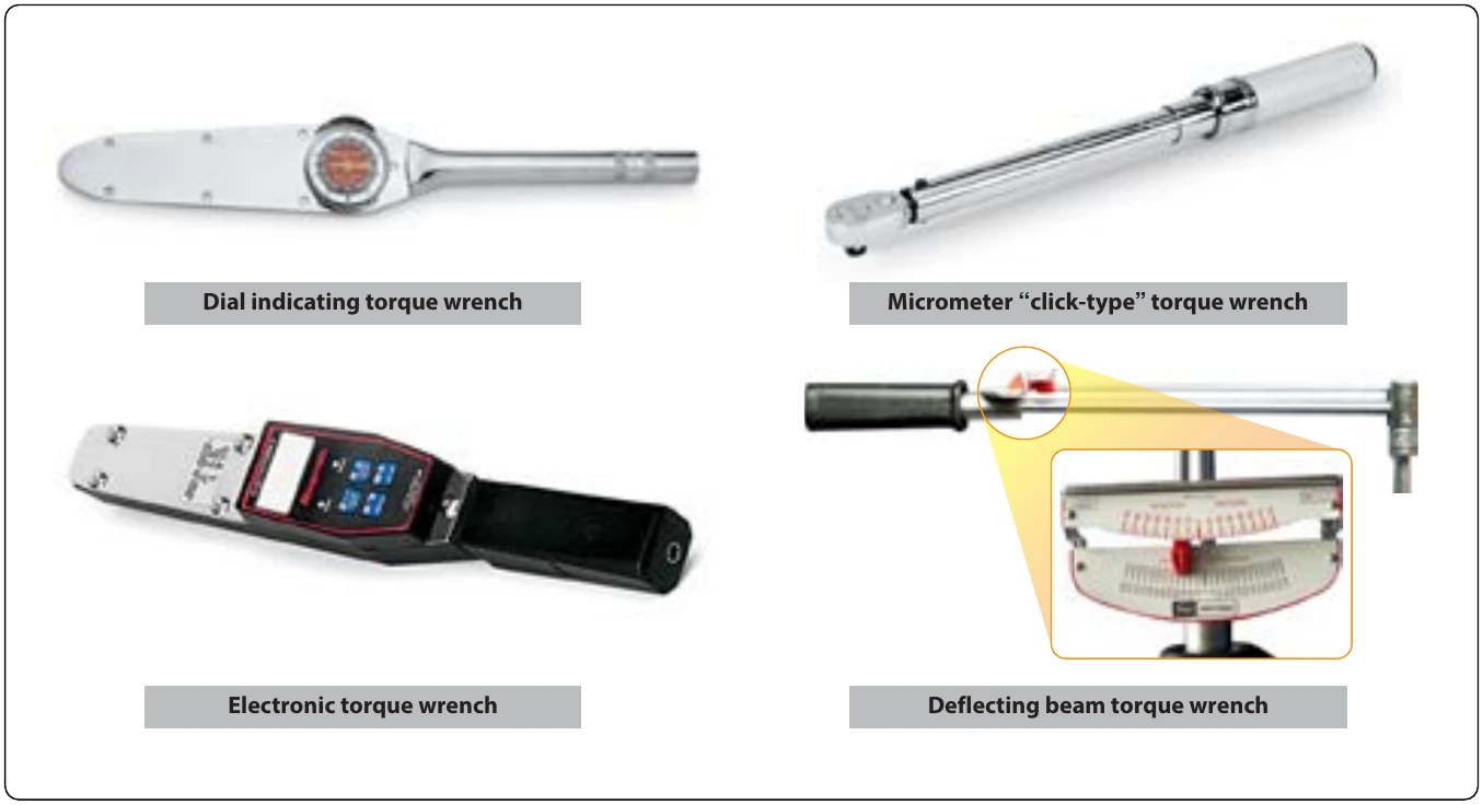
The three most commonly used torque wrenches are the deflecting beam, dial indicating, and micrometer setting types. [Figure 11-10] When using the deflecting beam and the dial indicating torque wrenches, the torque is read visually on a dial or scale mounted on the handle of the wrench. The micrometer setting torque wrench is preset to the desired torque. When this torque is reached, the operator notices a sharp impulse or breakaway “click.” For additional information on the installation of fasteners requiring the use of a torque wrench, refer to “Installation of Nuts, Washers, and Bolts” located in Chapter 7, Aircraft Materials, Processes and Hardware.
Strap Wrenches
The strap wrench can prove to be an invaluable tool for the AMT. By their very nature, aircraft components, such as tubing, pipes, small fittings, and round or irregularly-shaped components, are built to be as light as possible while still retaining enough strength to function properly. The misuse of pliers or other gripping tools can quickly damage these parts. If it is necessary to grip a part to hold it in place, or to rotate it to facilitate removal, consider using a strap wrench that uses a plastic covered fabric strap to grip the part. [Figure 11-11]
Impact Drivers
In certain applications, the use of an impact driver may be required. Struck with a mallet, the impact driver uses cam action to impart a high amount of torque in a sharp impact to break loose a stubborn fastener. The drive portion of the impact driver can accept a number of different drive bits and sockets. The use of special bits and sockets specifically manufactured for use with an impact driver is required. [Figure 11-12]
Metal Cutting Tools
Hand Snips
There are several kinds of hand snips, each of which serves a different purpose. Straight, curved, hawksbill, and aviation snips are in common use. Straight snips are used for cutting straight lines when the distance is not great enough to use a squaring shear and for cutting the outside of a curve. The other types are used for cutting the inside of curves or radii. Snips should never be used to cut heavy sheet metal. [Figure 11-13]
Aviation snips are designed especially for cutting heat-treated aluminum alloy and stainless steel. They are also adaptable for enlarging small holes. The blades have small teeth on the cutting edges and are shaped for cutting very small circles and irregular outlines. The handles are the compound leverage type, making it possible to cut material as thick as 0.051 inch. Aviation snips are available in two types: those which cut from right to left and those which cut from left to right.
Unlike the hacksaw, snips do not remove any material when the cut is made, but minute fractures often occur along the cut. Therefore, cuts should be made about 1⁄32 inch from the layout line and finished by hand filing down to the line.
Hacksaws
The common hacksaw has a blade, a frame, and a handle. The handle can be obtained in two styles: pistol grip and straight. [Figure 11-14]
Hacksaw blades have holes in both ends; they are mounted on pins attached to the frame. When installing a blade in a hacksaw frame, mount the blade with the teeth pointing forward, away from the handle.
Blades are made of high-grade tool steel or tungsten steel and are available in sizes from 6 to 16 inches in length. The 10-inch blade is most commonly used. There are two types: the all-hard blade and the flexible blade. In flexible blades, only the teeth are hardened.
Selection of the best blade for the job involves finding the right type and pitch. An all-hard blade is best for sawing brass, tool steel, cast iron, and heavy cross-section materials. A flexible blade is usually best for sawing hollow shapes and metals having a thin cross-section.
The pitch of a blade indicates the number of teeth per inch. Pitches of 14, 18, 24, and 32 teeth per inch are available. A blade with 14 teeth per inch is preferred when cutting machine steel, cold-rolled steel, or structural steel. A blade with 18 teeth per inch is preferred for solid stock aluminum, bearing metal, tool steel, and cast iron. Use a blade with 24 teeth per inch when cutting thick-walled tubing, pipe, brass, copper, channel, and angle iron. Use the 32 teeth per inch blade for cutting thin-walled tubing and sheet metal. When using a hacksaw, observe the following procedures:
- Select an appropriate saw blade for the job.
- Assemble the blade in the frame so that the cutting edge of the teeth points away from the handle.
- Adjust tension of the blade in the frame to prevent the saw from buckling and drifting.
- Clamp the work in the vise in such a way that provides as much bearing surface as possible and engages the greatest number of teeth.
- Indicate the starting point by nicking the surface with the edge of a file to break any sharp corner that might strip the teeth. This mark also aids in starting the saw at the proper place.
- Hold the saw at an angle that keeps at least two teeth in contact with the work at all times. Start the cut with a light, steady, forward stroke just outside the cutting line. At the end of the stroke, relieve the pressure and draw the blade back. (The cut is made only on the forward stroke.)
- After the first few strokes, make each stroke as long as the hacksaw frame allows. This prevents the blade from overheating. Apply just enough pressure on the