
Chapter 12
Fundamentals of Electricity & Electronics
- Positive (regenerative)
- Negative (degenerative)
The main difference between these two signals is whether the feedback signal adds to the input signal or if the feedback signal diminishes the input signal.
When the feedback is positive, the signal being returned to the input is in phase with the input signal and thus interferes constructively. Figure 12-245 illustrates this concept applied in the amplified circuit through a block diagram. Notice that the feedback signal is in phase with the input signal, which regenerates the input signal. This results in an output signal with amplitude greater than would have been without the constructive, positive feedback. This type of positive feedback is what causes an audio system to squeal.
Figure 12-245 also illustrates with a block diagram how negative or degenerative feedback occurs. In this case, the feedback signal is out of phase with the input signal. This causes destructive interference and degenerates the input signal. The result is a lower amplitude output signal than would have occurred without the feedback.
Operational Amplifiers (OP AMP)
An operational amplifier (OP AMP) is designed to be used with other circuit components and performs either computing functions or filtering. [Figure 12-246] Operational amplifiers are usually high-gain amplifiers with the amount of gain governed by the amount of feedback.
Operational amplifiers were originally developed for analog computers and used to perform mathematical functions. Today many devices use the operational amplifier for DC amplifiers, AC amplifiers, comparators, oscillators, and filter circuits. The widespread use is due to the fact that the OP AMP is a versatile device, small, and inexpensive. Built into the integrated chip, the operational amp is used as a basic building block of larger circuits.
There are two inputs to the operational amplifier, inverting (−) and non-inverting (+), and there is one output. The polarity amplifier, the circuit must have certain characteristics:
- Very high gain
- Very high input impedance
- Very high output impedance
This type of a circuit can be made up of discrete components, such as resistors and transistors. However, the most common form of an operational amplifier is found in the integrated circuit. This integrated circuit or chip contains the various stages of the operational amplifier and can be treated as if it were a single stage.
Applications
The number of applications for OP AMPs is too numerous to detail in this handbook. However, the technician occasionally comes across these devices in modern aircraft and should be able to recognize their general purpose in a circuit. Some of the basic applications are:
- Go/no-go detectors
- Square wave circuits
- Non-inverting amplifier
- Inverting amplifier
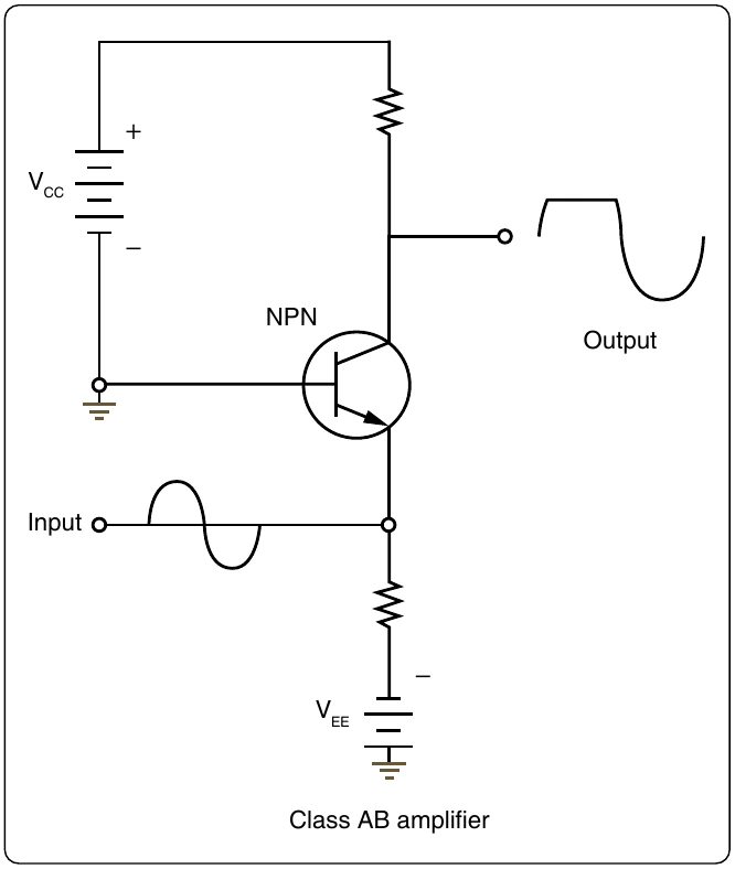
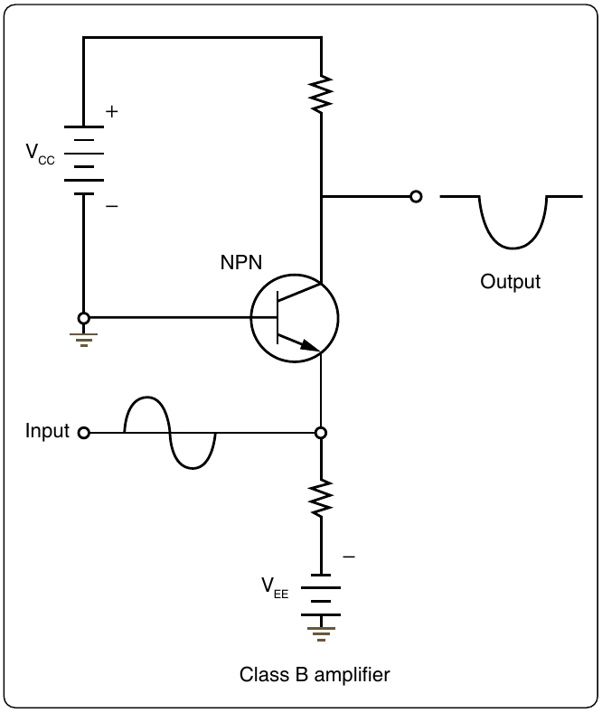
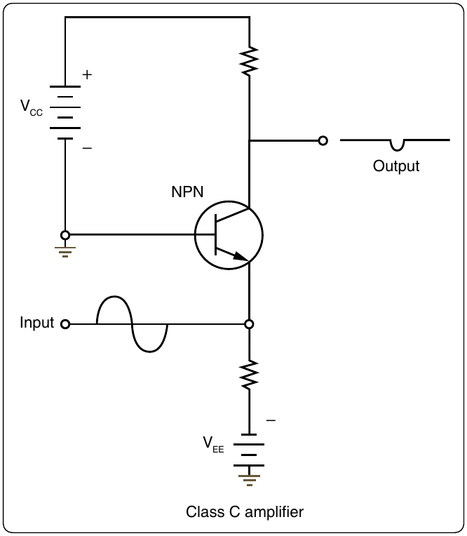
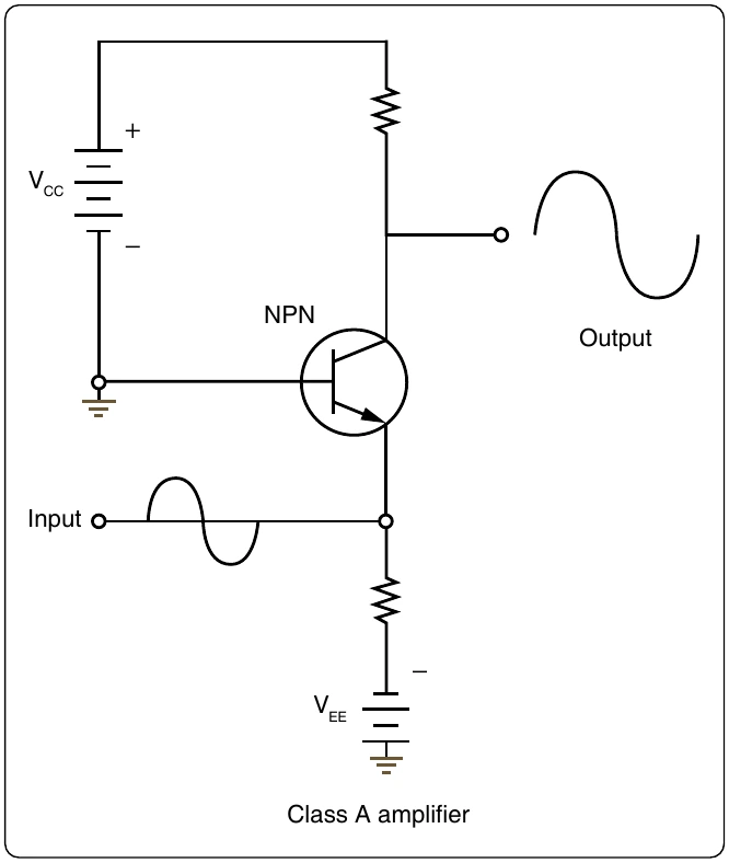
magnetic amplifier is a power amplifier with a very limited frequency response. The frequency range most commonly associated with the magnetic amplifier is 100 Hz and less, which places it in the audio range. As a technical point, the magnetic amplifier is a low-frequency amplifier.
Advantages of the magnetic amplifier are:
- Very high efficiency, on the order of approximately 90 percent
- High reliability
- Very rugged, able to withstand vibrations, moisture, and overloads
- No warm-up time