Chapter 4
Engine Ignition & Electrical Systems
Where the use of placards or monitoring devices is not practical or desired, and where assurance is needed that the battery in a typical small aircraft generator or battery power source is charged in flight, the total continuous connected electrical load may be held to approximately 80 percent of the total rated generator output capacity. When more than one generator is used in parallel, the total rated output is the combined output of the installed generators.
Means must be provided for quickly coping with the sudden overloads that can be caused by generator or engine failure if two or more generators are operated in parallel and the total connected system load can exceed the rated output of one generator. A quick load-reduction system can be employed or a specified procedure where the total load is reduced to a quantity that is within the rated capacity of the remaining operable generator or generators.
Electrical loads should be connected to inverters, alternators, or similar aircraft electrical power sources in such a manner that the rated limits of the power source are not exceeded, unless some type of effective monitoring means is provided to keep the load within prescribed limits.
Circuit Protection Devices
Conductors should be protected with circuit breakers or fuses located as close as possible to the electrical power source bus. Normally, the manufacturer of the electrical equipment specifies the fuse or circuit breaker to be used when installing the equipment.
The circuit breaker or fuse should open the circuit before the conductor emits smoke. To accomplish this, the time/current characteristic of the protection device must fall below that of the associated conductor. Circuit protector characteristics should be matched to obtain the maximum utilization of the connected equipment.
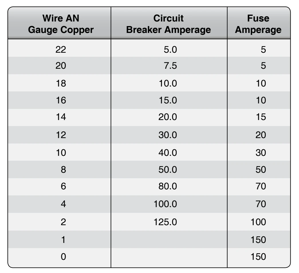
Figure 4-124 shows an example of the table used in selecting the circuit breaker and fuse protection for copper conductors. This limited table is applicable to a specific set of ambient temperatures and wire bundle sizes and is presented as a typical example only. It is important to consult such guides before selecting a conductor for a specific purpose. For example, a wire run individually in the open air may be protected by the circuit breaker of the next higher rating to that shown in the table.
All resettable circuit breakers should open the circuit in which they are installed, regardless of the position of the operating control when an overload or circuit fault exists. Such circuit breakers are referred to as trip-free. Automatic reset circuit breakers automatically reset themselves periodically. They should not be used as circuit protection devices in aircraft.
Switches
A specifically designed switch should be used in all circuits in which a switch malfunction would be hazardous. Such switches are of rugged construction and have sufficient contact capacity to break, make, and carry continuously the connected load current. Snap-action design is generally preferred to obtain rapid opening and closing of contacts regardless of the speed of the operating toggle or plunger, thereby minimizing contact arcing.
The nominal current rating of the conventional aircraft switch is usually stamped on the switch housing. This rating represents the continuous current rating with the contacts closed. Switches should be derated from their nominal current rating for the following types of circuits:
- High rush-in circuits—circuits containing incandescent lamps can draw an initial current that is 15 times greater than the continuous current. Contact burning or welding may occur when the switch is closed.
- Inductive circuits—magnetic energy stored in solenoid coils or relays is released and appears as an arc as the control switch is opened.
- Motors—direct current motors draw several times their rated current during starting, and magnetic energy stored in their armature and field coils is released when the control switch is opened.
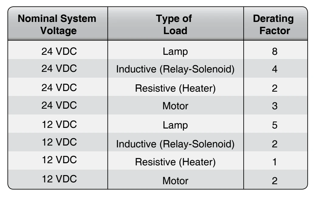
Figure 4-125 is typical of those tables available for selecting the proper nominal switch rating when the continuous load current is known. This selection is essentially a derating to obtain reasonable switch efficiency and service life.
Hazardous errors in switch operation can be avoided by logical and consistent installation. Two position on-off switches should be mounted so that the on position is reached by an upward or forward movement of the toggle. When the switch controls movable aircraft elements, such as landing gear or flaps, the toggle should move in the same direction as the desired motion. Inadvertent operation of a switch can be prevented by mounting a suitable guard over the switch.
Relays
Relays are used as switching devices in which a weight reduction can be achieved or electrical controls can be simplified. A relay is an electrically operated switch and is therefore subject to dropout under low system voltage conditions. The previous discussion of switch ratings is generally applicable to relay contact ratings.