Chapter 7
Propellers
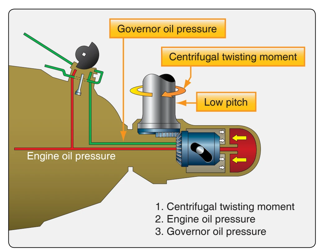
The propeller piston moves outboard under the auxiliary oil pressure at a speed proportional to the rate the oil is supplied. This piston motion is transmitted through the piston rollers operating in the oppositely inclined cam tracks of the fixed cam and the rotating cam and is converted by the bevel gears into the blade-twisting moment. Only during feathering or unfeathering is the low mechanical advantage portion of the cam tracks used. (The low mechanical advantage portion lies between the break and the outboard end of the track profile.) Oil at engine pressure, displaced from the outboard piston end, flows through the distributor valve outboard inlet, past the outboard end of the valve land, through the valve port, into the propeller shaft engine oil passage, and is finally delivered into the engine lubricating system. Thus, the blades move toward the full high-pitch (or feathered) angle.
Having reached the full-feathered position, further movement of the mechanism is prevented by contact between the highangle stop ring in the base of the fixed cam and the stop lugs set in the teeth of the rotating cam. The pressure in the inboard piston end now increases rapidly, and upon reaching a set pressure, the electric cutout switch automatically opens.
This cutout pressure is less than that required to shift the distributor valve.
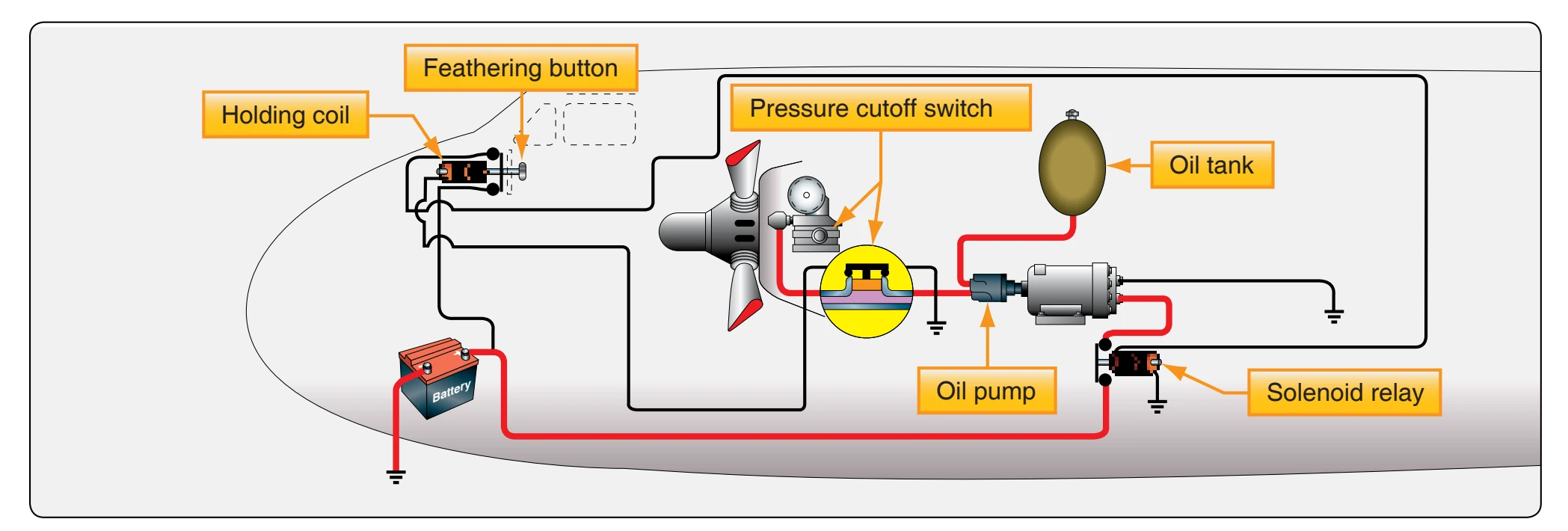
Opening the switch deenergizes the holding coil and releases the feathering push-button control switch. Release of this switch breaks the solenoid relay circuit, which shuts off the feathering pump motor. The pressures in both the inboard and outboard ends of the piston drop to zero, and, since all the forces are balanced, the propeller blades remain in the feathered position. Meanwhile, the governor high-pressure transfer valve has shifted to its normal position as soon as the pressure in the propeller governor line drops below that required to hold the valve open.
Unfeathering Operation
To unfeather a hydromatic propeller, depress and hold in the feathering switch push-button control switch. As in the case of feathering a propeller, the low-current control circuits from the battery through the holding coil and from the battery through the solenoid are completed when the solenoid closes. The high-current circuit from the battery starts the motor-pump unit, and oil is supplied at a high pressure to the governor transfer valve.
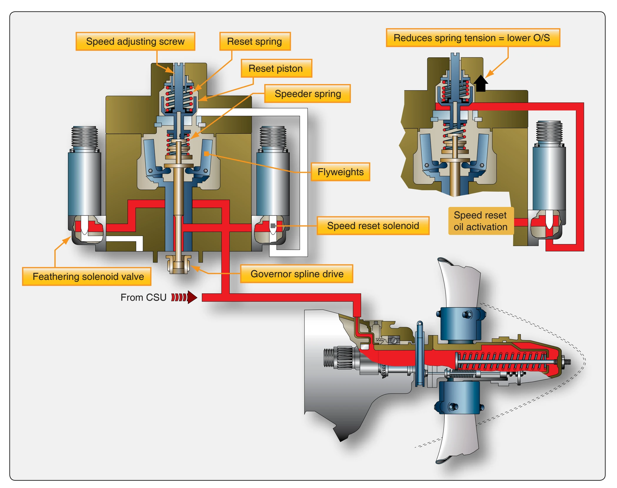
Auxiliary oil entering through the high-pressure transfer valve connection shifts the governor transfer valve and disconnects the governor from the propeller line; in the same operation, auxiliary oil is admitted. The oil flows through the engine oil transfer rings, through the propeller shaft governor oil passage, and into the distributor valve assembly.
When the unfeathering operation begins, the piston is in the extreme outboard position. The oil enters the inboard piston end of the cylinder by way of the distributor valve inboard outlet. As the pressure on the inboard end of the piston increases, the pressure against the distributor valve land builds up. When the pressure becomes greater than the combined opposing force of the distributor valve spring and the oil pressure behind this spring, the valve shifts. Once the valve shifts, the passages through the distributor valve assembly to the propeller are reversed. A passage is opened between lands and through a port to the outboard piston end by way of the distributor valve outlet. As the piston moves inboard under the auxiliary pump oil pressure, oil is displaced from the inboard piston end through the inlet ports between the valve lands, into the propeller shaft engine oil lands, and into the propeller shaft engine oil passage where it is discharged into the engine lubricating system. At the same time, the pressure at the cutout switch increases and the switch opens. However, the circuit to the feathering pump and motor unit remains complete as long as the feathering switch is held in.
With the inboard end of the propeller piston connected to drain and auxiliary pressure flowing to the outboard end of the piston, the piston moves inboard, unfeathering the blades. As the blades are unfeathered, they begin to windmill and assist the unfeathering operation by the added force toward low pitch brought about by the centrifugal twisting moment. When the engine speed has increased to approximately 1,000 rpm, the operator shuts off the feathering pump motor. The pressure in the distributor valve and at the governor transfer valve decreases, allowing the distributor valve to shift under the action of the governor high-pressure transfer valve spring. This action reconnects the governor with the propeller and
establishes the same oil passages through the distributor valve that are used during constant-speed and feathering operations.
Setting the Propeller Governor
The propeller governor incorporates an adjustable stop that limits the maximum speed at which the engine can run. As soon as the takeoff rpm is reached, the propeller moves off the low-pitch stop. The larger propeller blade angle increases the load on the engine, thus maintaining the prescribed maximum engine speed. At the time of propeller, propeller governor, or engine installation, the following steps are normally taken to ensure that the powerplant obtains takeoff rpm. During ground runup, move the throttle to takeoff position and note the resultant rpm and manifold pressure. If the rpm obtained is higher or lower than the takeoff rpm prescribed in the manufacturer’s instructions, reset the adjustable stop on the governor until the prescribed rpm is obtained.