
Chapter 3
Helicopter Flight Controls
Introduction
There are three major controls in a helicopter that the pilot must use during flight. They are the collective pitch control, the cyclic pitch control, and the antitorque pedals or tail rotor control. In addition to these major controls, the pilot must also use the throttle control, which is usually mounted directly to the collective pitch control in order to fly the helicopter.
In this chapter, the control systems described are not limited to the single main rotor type helicopter but are employed in one form or another in most helicopter configurations. All examples in this chapter refer to a counterclockwise main rotor blade rotation as viewed from above. If flying a helicopter with a clockwise rotation, left and right references must be reversed, particularly in the areas of rotor blade pitch change, antitorque pedal movement, and tail rotor thrust.
Collective Pitch Control
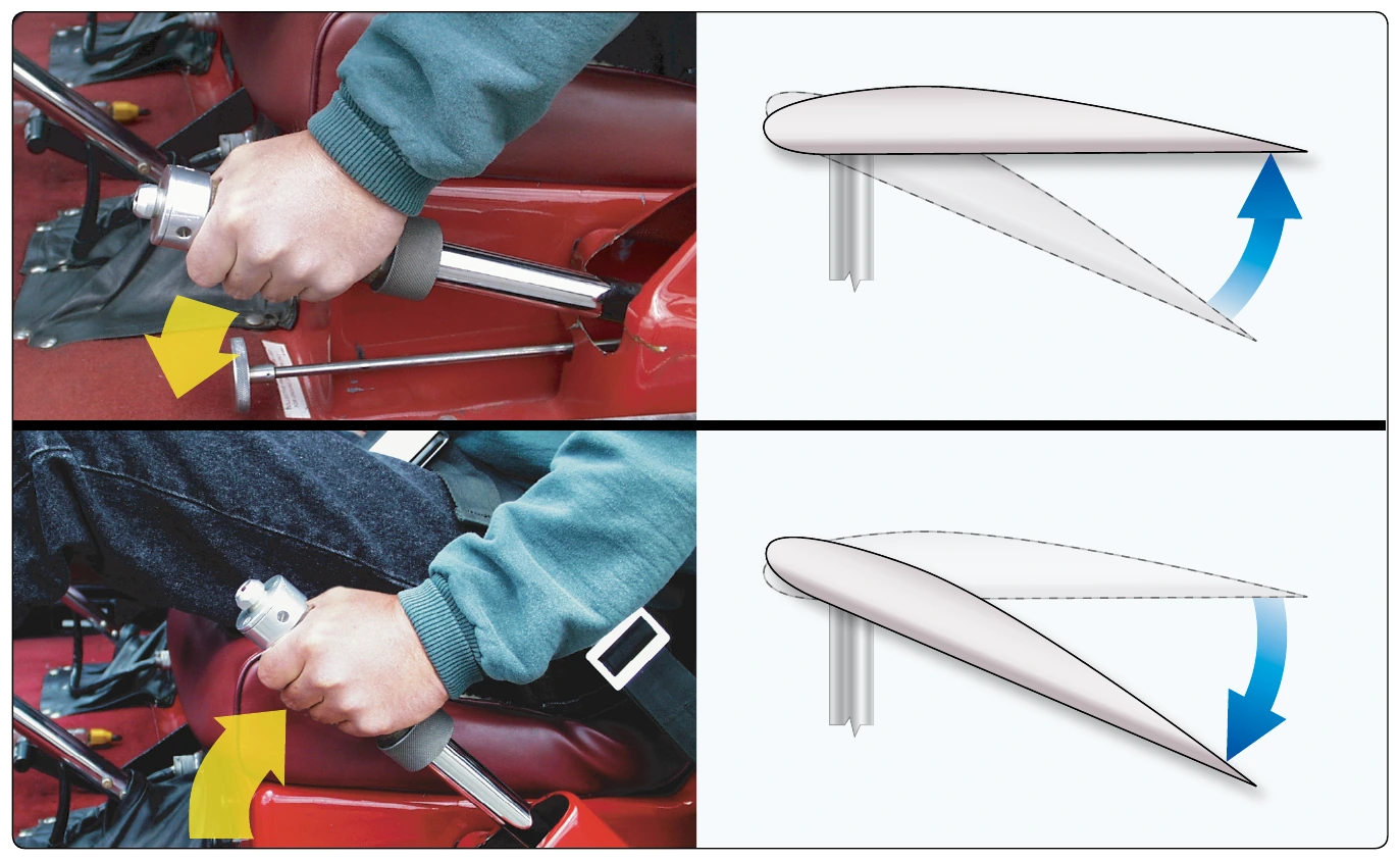
The collective pitch control (or simply “collective” or “thrust lever”) is located on the left side of the pilot’s seat and is operated with the left hand. The collective is used to make changes to the pitch angle of the main rotor blades and does this simultaneously, or collectively, as the name implies. As the collective pitch control is raised, there is a simultaneous and equal increase in pitch angle of all main rotor blades; as it is lowered, there is a simultaneous and equal decrease in pitch angle. This is done through a series of mechanical linkages and the amount of movement in the collective lever determines the amount of blade pitch change. [Figure 3-1] An adjustable friction control helps prevent inadvertent collective pitch movement.
Changing the pitch angle on the blades changes the angle of incidence on each blade. With a change in angle of incidence comes a change in drag, which affects the speed or revolutions per minute (rpm) of the main rotor. As the pitch angle increases, angle of incidence increases, drag increases, and rotor rpm decreases. Decreasing pitch angle decreases both angle of incidence and drag, while rotor rpm increases. In order to maintain a constant rotor rpm, which is essential in helicopter operations, a proportionate change in power is required to compensate for the change in drag. This is accomplished with the throttle control or governor, which automatically adjusts engine power.
Throttle Control
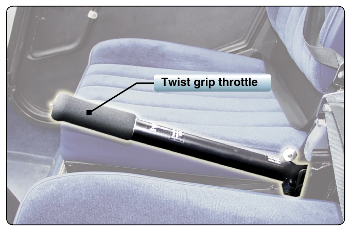
The function of the throttle is to regulate engine rpm. If the correlator or governor system does not maintain the desired rpm when the collective is raised or lowered, or if those systems are not installed, the throttle must be moved manually with the twist grip in order to maintain rpm. In most helicopters, rotating the twist-grip throttle away from the pilot (counter-clockwise), increases engine rpm; rotating the twist-grip throttle towards the pilot (clockwise) decreases engine rpm. [Figure 3-2]
Governor/Correlator
A governor is a sensing device that senses rotor and engine rpm and makes the necessary adjustments in order to keep rotor rpm constant. In normal operations, once the rotor rpm is set, the governor keeps the rpm constant, and there is no need to make any throttle adjustments. Governors are common on all turbine helicopters (as it is a function of the fuel control system of the turbine engine) and used on some piston powered helicopters.
A correlator is a mechanical connection between the collective lever and the engine throttle. When the collective lever is raised, power is automatically increased; when lowered, power is decreased. This system maintains rpm close to the desired value, but still requires adjustment of the throttle for fine tuning.
Some helicopters do not have correlators or governors and require coordination of all collective and throttle movements. When the collective is raised, the throttle must be increased; when the collective is lowered, the throttle must be decreased. As with any aircraft control, large adjustments of either collective pitch or throttle should be avoided. All corrections should be made through the use of smooth pressure.
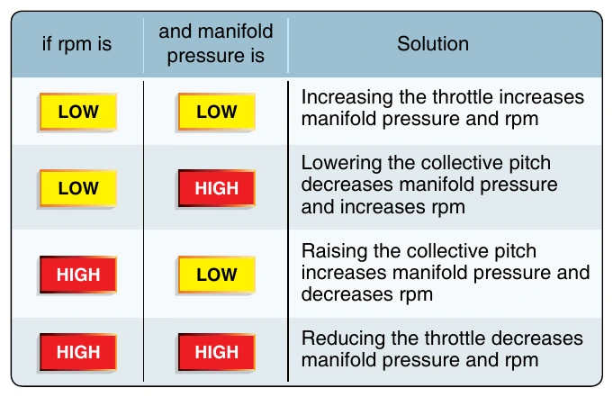
In piston helicopters, the collective pitch is the primary control for manifold pressure, and the throttle is the primary control for rpm. However, the collective pitch control also influences rpm, and the throttle also influences manifold pressure; therefore, each is considered to be a secondary control of the other’s function. Both the tachometer (rpm indicator) and the manifold pressure gauge must be analyzed to determine which control to use. Figure 3-3 illustrates this relationship.
Cyclic Pitch Control
The cyclic pitch control (or simply “cyclic”) is usually projected upward from the cockpit floor, between the pilot’s legs or between the two pilot seats in some models. [Figure 3-4] This primary flight control allows the pilot to fly the helicopter in any direction of travel: forward, rearward, left, and right. As discussed in Chapter 2, Aerodynamics of Flight, the total lift force is always perpendicular to the tip-path plane of the main rotor. The purpose of the cyclic pitch control is to tilt the tip-path plane in the direction of the desired horizontal direction. The cyclic controls the rotor disk tilt versus the horizon, which directs the rotor disk thrust to enable the pilot to control the direction of travel of the helicopter.
The rotor disk tilts in the same direction the cyclic pitch control is moved. If the cyclic is moved forward, the rotor disk tilts forward; if the cyclic is moved aft, the disk tilts aft, and so on. Because the rotor disk acts like a gyro, the mechanical linkages for the cyclic control rods are rigged in such a way that they decrease the pitch angle of the rotor blade approximately 90° before it reaches the direction of cyclic displacement and increase the pitch angle of the rotor blade approximately 90° after it passes the direction of displacement. An increase in pitch angle increases AOA; a decrease in pitch angle decreases AOA. For example, if the cyclic is moved forward, the AOA decreases as the rotor blade passes the right side of the helicopter and increases on the left side. This results in maximum downward deflection of the rotor blade in front of the helicopter and maximum upward deflection behind it, causing the rotor disk to tilt forward.