
Chapter 4
Helicopter Components, Sections, and Systems
The rigid rotor system is very responsive and is usually not susceptible to mast bumping like the semirigid systems because the rotor hubs are mounted solid to the main rotor mast. This allows the rotor and fuselage to move together as one entity and eliminates much of the oscillation usually present in the other rotor systems. Other advantages of the rigid rotor include a reduction in the weight and drag of the rotor hub and a larger flapping arm, which significantly reduces control inputs. Without the complex hinges, the rotor system becomes much more reliable and easier to maintain than the other rotor configurations. A disadvantage of this system is the quality of ride in turbulent or gusty air. Because there are no hinges to help absorb the larger loads, vibrations are felt in the cabin much more than with other rotor head designs.
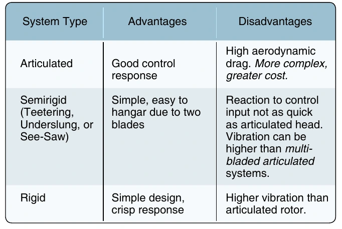
There are several variations of the basic three rotor head designs. The bearingless rotor system is closely related to the articulated rotor system but has no bearings or hinges. This design relies on the structure of blades and hub to absorb stresses. The main difference between the rigid rotor system and the bearingless system is that the bearingless system has no feathering bearing—the material inside the cuff is twisted by the action of the pitch change arm. Nearly all bearingless rotor hubs are made of fiber-composite materials. The differences in handling between the types of rotor system are summarized in Figure 4-5.
Fully Articulated Rotor System
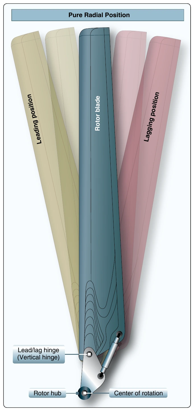
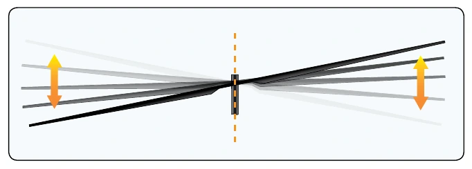
Fully articulated rotor systems allow each blade to lead/lag (move back and forth in plane), flap (move up and down about an inboard mounted hinge) independent of the other blades, and feather (rotate about the pitch axis to change lift). [Figures 4-6 and 4-7] Each of these blade motions is related to the others. Fully articulated rotor systems are found on helicopters with more than two main rotor blades.
As the rotor spins, each blade responds to inputs from the control system to enable aircraft control. The center of lift on the whole rotor system moves in response to these inputs to effect pitch, roll, and upward motion. The magnitude of this lift force is based on the collective input, which changes pitch on all blades in the same direction at the same time. The location of this lift force is based on the pitch and roll inputs from the pilot. Therefore, the feathering angle of each blade (proportional to its own lifting force) changes as it rotates with the rotor, hence the name “cyclic control.”
As the lift on a given blade increases, it tends to flap upwards. The flapping hinge for the blade permits this motion and is balanced by the centrifugal force of the weight of the blade, which tries to keep it in the horizontal plane. [Figure 4-8]
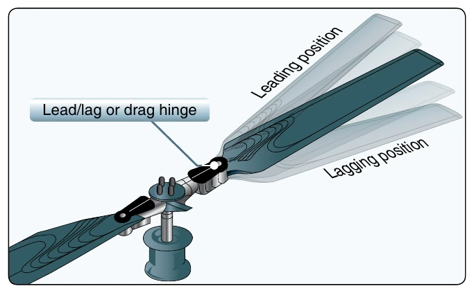
Either way, some motion must be accommodated. The centrifugal force is nominally constant; however, the flapping force is affected by the severity of the maneuver (rate of climb, forward speed, aircraft gross weight). As the blade flaps, its CG changes. This changes the local moment of inertia of the blade with respect to the rotor system and it speeds up or slows down with respect to the rest of the blades and the whole rotor system. This is accommodated by the lead/lag or drag hinge, shown in Figure 4-9, and is easier to visualize with the classical ‘ice skater doing a spin’ image. As the skater moves her arms in, she spins faster because her inertia changes but her total energy remains constant (neglect friction for purposes of this explanation). Conversely, as her arms extend, her spin slows. This is also known as the conservation of angular momentum. An in-plane damper typically moderates lead/lag motion.
Following a single blade through a single rotation beginning at some neutral position, as load increases from increased feathering, it flaps up and leads forward. As it continues around, it flaps down and lags backward. At the lowest point of load, it is at its lowest flap angle and also at its most ‘rearward’ lag position. Because the rotor is a large, rotating mass, it behaves somewhat like a gyroscope. The effect of this is that a control input is usually realized on the attached body at a position 90° prior to the control input displacement in the axis of rotation. This is accounted for by the designers through placement of the control input to the rotor system so that a forward input of the cyclic control stick results in a nominally forward motion of the aircraft. The effect is made transparent to the pilot.
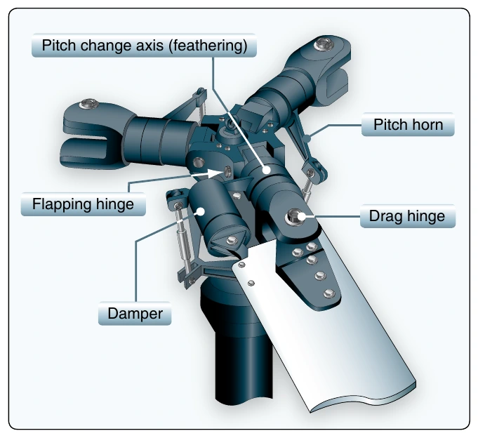
Older hinge designs relied on conventional metal bearings. By basic geometry, this precludes a coincident flapping and lead/lag hinge and is cause for recurring maintenance. Newer rotor systems use elastomeric bearings, arrangements of rubber and steel that can permit motion in two axes. Besides solving some of the above-mentioned kinematic issues, these bearings are usually in compression, can be readily inspected, and eliminate the maintenance associated with metallic bearings.
Elastomeric bearings are naturally fail-safe, and their wear is gradual and visible. The metal-to-metal contact of older bearings and the need for lubrication is eliminated in this design.
Tandem Rotor
Tandem rotor (sometimes referred to as dual rotor) helicopters have two large horizontal rotor assemblies; a twin rotor system, instead of one main assembly, and a smaller tail rotor. [Figure 4-10] Single rotor helicopters need an anti-torque system to neutralize the twisting momentum produced by the single large rotor. Tandem rotor helicopters, however, use counter-rotating rotors, with each canceling out the other’s torque. Counter-rotating rotor blades will not collide with and destroy each other if they flex into the other rotor’s pathway. This configuration also has the advantage of being able to hold more weight with shorter blades, since there are two sets. Also, all of the power from the engines can be used for lift, whereas a single rotor helicopter uses power to counter the torque.
Coaxial Rotors
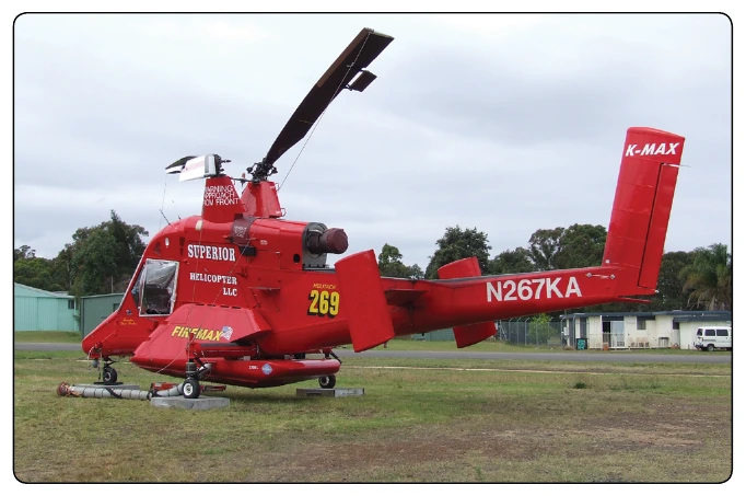
A coaxial rotor system is a pair of rotors mounted on the same shaft but turning in opposite directions. This design eliminates the need for a tail rotor or other antitorque mechanisms, and since the blades turn in opposite directions, the effects of dissymmetry of lift are avoided. The main disadvantage of coaxial rotors is the increased mechanical complexity of the rotor system. Numerous Russian helicopters, such as the Kaman Ka-31 and Ka-50, along with the Sikorsky experimental X2 use a coaxial rotor design.