Chapter 5
Rotorcraft Flight Manual
Altitude Limitations
If the rotorcraft has a maximum operating density altitude (see page 7-2), it is indicated in this section of the flight manual. Sometimes the maximum altitude varies based on different gross weights.
Rotor Limitations
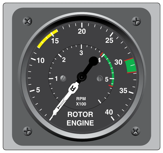
Low rpm does not produce sufficient lift, and high rpm may cause structural damage, therefore rotor rpm limitations have minimum and maximum values. A green arc depicts the normal operating range with red lines showing the minimum and maximum limits. [Figure 5-3]
There are two different rotor rpm limitations: power-on and power-off. Power-on limitations apply anytime the engine is turning the rotor and is depicted by a fairly narrow green band. A yellow arc may be included to show a transition range, which means that operation within this range is limited due to the possibility of increased vibrations or harmonics. This range may be associated with tailboom dynamic modes. Power-off limitations apply anytime the engine is not turning the rotor, such as when in an autorotation. In this case, the green arc is wider than the power-on arc, indicating a larger operating range.
Powerplant Limitations
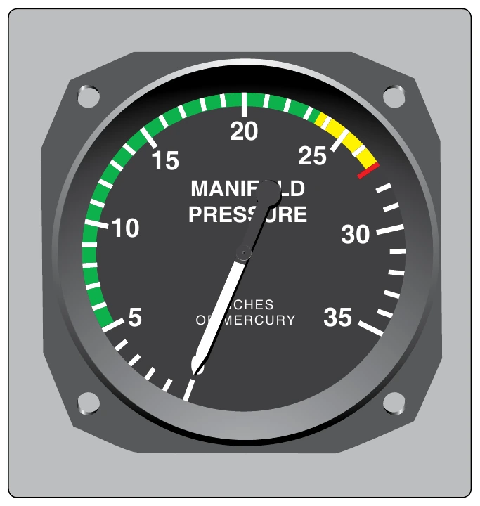
The powerplant limitations area describes operating limitations on the helicopter’s engine including such items as rpm range, power limitations, operating temperatures, and fuel and oil requirements. Most turbine engines and some reciprocating engines have a maximum power and a maximum continuous power rating. The “maximum power” rating is the maximum power the engine can generate and is usually limited by time. The maximum power range is depicted by a yellow arc on the engine power instruments, with a red line indicating the maximum power that must not be exceeded. “Maximum continuous power” is the maximum power the engine can generate continually and is depicted by a green arc. [Figure 5-4]
Manifold pressure is a measure of vacuum at the intake manifold. It is the difference between the air pressure (or vacuum) inside the intake manifold and the relative atmospheric pressure of the air around the engine. The red line on a manifold pressure gauge indicates the maximum amount of power. A yellow arc on the gauge warns of pressures approaching the limit of rated power.
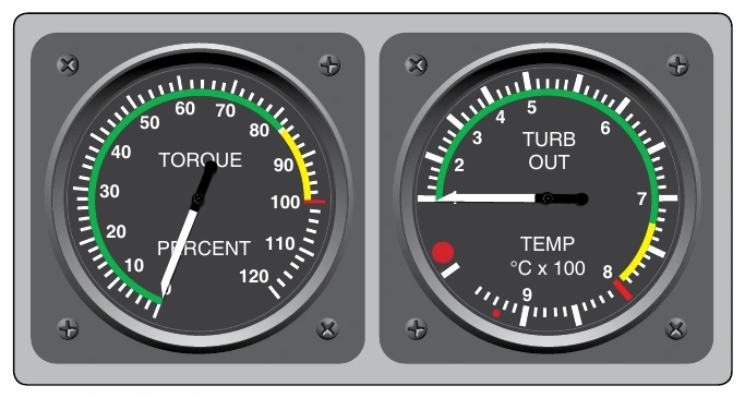
[Figure 5-5] A placard near the gauge lists the maximum readings for specific conditions.
Weight and Loading Distribution
The weight and loading distribution section of the manufacturer's RFM contains the maximum certificated weights, as well as the center of gravity (CG) range. The location of the reference datum used in balance computations should also be included in this section. Weight and balance computations are not provided here, but rather in the weight and balance section of the RFM.
Flight Limitations
This area lists any maneuvers which are prohibited, such as acrobatic flight or flight into known icing conditions. If the rotorcraft can only be flown in visual flight rules (VFR) conditions, it is noted in this area. Also included are the minimum crew requirements, and the pilot seat location, if applicable, from which solo flights must be conducted.
Placards
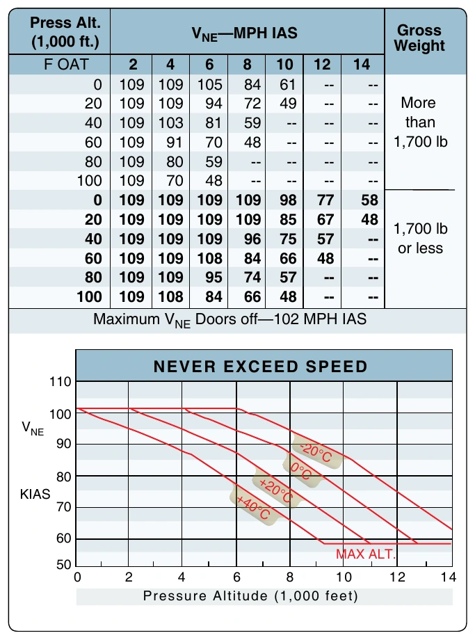
All rotorcraft generally have one or more placards displayed that have a direct and important bearing on the safe operation of the rotorcraft. These placards are located in a conspicuous place within the cabin and normally appear in the limitations section. Since VNE varies with altitude, this placard can be found in all helicopters. [Figure 5-6]