Chapter 4
Aerodynamic Factors
Introduction
Several factors affect aircraft performance including the atmosphere, aerodynamics, and aircraft icing. Pilots need an understanding of these factors for a sound basis for prediction of aircraft response to control inputs, especially with regard to instrument approaches, while holding, and when operating at reduced airspeed in instrument meteorological conditions (IMC). Although these factors are important to the pilot flying visual flight rules (VFR), they must be even more thoroughly understood by the pilot operating under instrument flight rules (IFR). Instrument pilots rely strictly on instrument indications to precisely control the aircraft; therefore, they must have a solid understanding of basic aerodynamic principles in order to make accurate judgments regarding aircraft control inputs.
The Wing
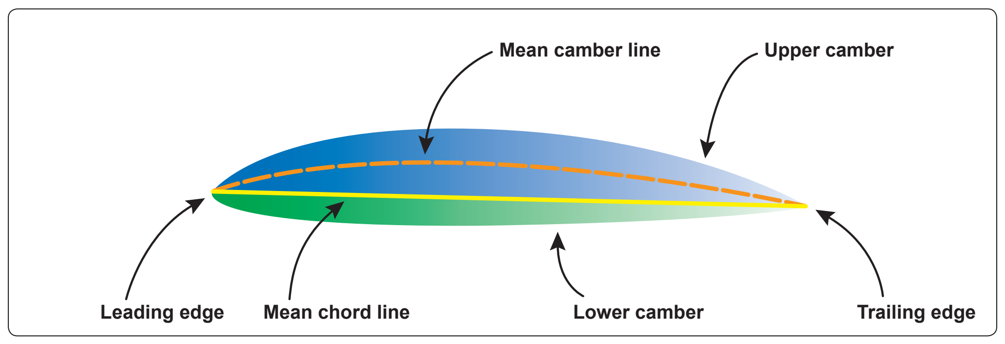
To understand aerodynamic forces, a pilot needs to understand basic terminology associated with airfoils. Figure 4-1 illustrates a typical airfoil.
The chord line is the straight line intersecting the leading and trailing edges of the airfoil, and the term chord refers to the chord line longitudinal length (length as viewed from the side).
The mean camber is a line located halfway between the upper and lower surfaces. Viewing the wing edgewise, the mean camber connects with the chord line at each end. The mean camber is important because it assists in determining aerodynamic qualities of an airfoil. The measurement of the maximum camber; inclusive of both the displacement of the mean camber line and its linear measurement from the end of the chord line, provide properties useful in evaluating airfoils.
Review of Basic Aerodynamics
The instrument pilot must understand the relationship and differences between several factors that affect the performance of an aircraft in flight. Also, it is crucial to understand how the aircraft reacts to various control and power changes, because the environment in which instrument pilots fly has inherent hazards not found in visual flying. The basis for this understanding is found in the four forces acting on an aircraft and Newton’s Three Laws of Motion.
Relative Wind is the direction of the airflow with respect to an airfoil.
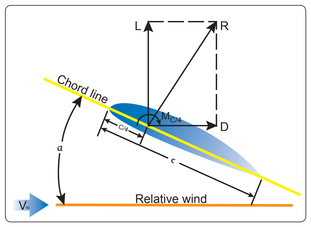
Angle of Attack (AOA) is the acute angle measured between the relative wind, or flightpath and the chord of the airfoil. [Figure 4-2] Flightpath is the course or track along which the aircraft is flying or is intended to be flown.
The Four Forces
The four basic forces [Figure 4-3] acting upon an aircraft in flight are lift, weight, thrust, and drag.
Lift
Lift is a component of the total aerodynamic force on an airfoil and acts perpendicular to the relative wind. Relative wind is the direction of the airflow with respect to an airfoil. This force acts straight up from the average (called mean) center of pressure (CP), which is called the center of lift. It should be noted that it is a point along the chord line of an airfoil through which all aerodynamic forces are considered to act. The magnitude of lift varies proportionately with speed, air density, shape and size of the airfoil, and AOA. During straight-and-level flight, lift and weight are equal.
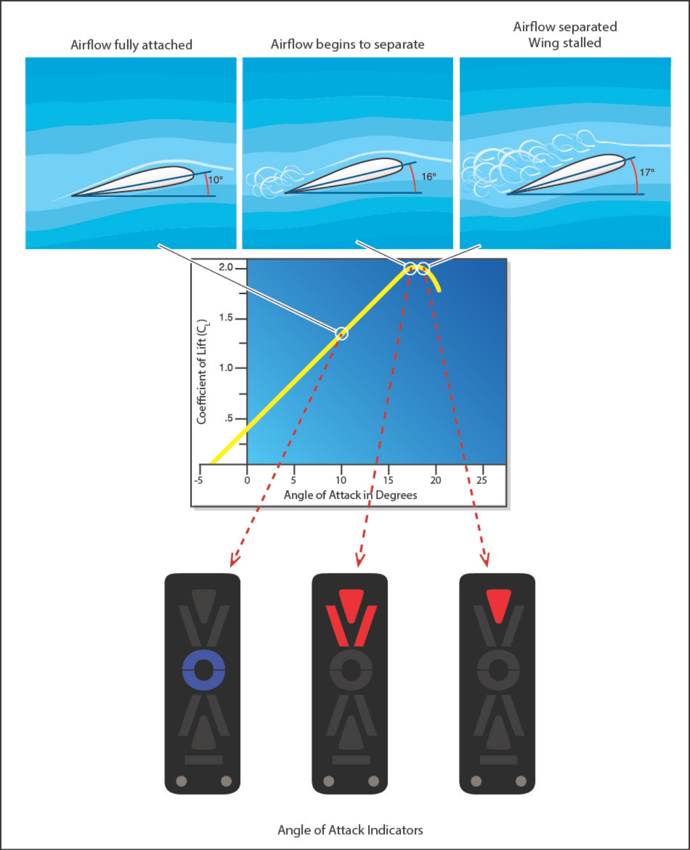
The FAA along with the General Aviation Joint Steering Committee (GAJSC) is promoting Angle of Attack (AOA) indicators as one of the many safety initiatives aimed at reducing the General Aviation accident rate. AOA indicators will specifically target Loss of Control (LOC) accidents. Loss of control is the number one root cause of fatalities in both General Aviation (GA) and Commercial Aviation. More than 25% of General Aviation fatal accidents occur during the maneuvering phase of flight. Of those accidents-half involve stall/spin scenarios. Technology such as AOA indicators can have a tremendous impact on reversing this trend and are increasingly affordable for GA airplanes.
The purpose of an AOA indicator is to give the pilot better situational awareness pertaining to the aerodynamic health of the airfoil. This can also be referred as stall margin awareness. More simply explained, it is the margin that exists between the current AOA that the airfoil will stall (critical AOA).