
Chapter 4
Approaches
Operational experience and research have shown that a descent rate of greater than approximately 1,000 fpm is unacceptable during the final stages of an approach (below 1,000 feet AGL). This is due to a human perceptual limitation that is independent of the type of airplane or helicopter. Therefore, the operational practices and techniques must ensure that descent rates greater than 1,000 fpm are not permitted in either the instrument or visual portions of an approach and landing operation.
For short runways, arriving at the MDA at the MAP when the MAP is located at the threshold may require a missed approach for some aircraft. For non-precision approaches, a descent rate should be used that ensures the aircraft reaches the MDA at a distance from the threshold that allows landing in the TDZ. On many IAPs, this distance is annotated by a VDP. If no VDP is annotated, calculate a normal descent point to the TDZ. To determine the required rate of descent, subtract the TDZE from the FAF altitude and divide this by the time inbound. For example, if the FAF altitude is 2,000 feet MSL, the TDZE is 400 feet MSL and the time inbound is two minutes, an 800 fpm rate of descent should be used.
To verify the aircraft is on an approximate three degree glidepath, use a calculation of 300 feet to 1 NM. The glidepath height above TDZE is calculated by multiplying the NM distance from the threshold by 300. For example, at 10 NM the aircraft should be 3,000 feet above the TDZE, at 5 NM the aircraft should be 1,500 feet above the TDZE, at 2 NM the aircraft should be 600 feet above the TDZE, and at 1.5 NM the aircraft should be 450 feet above the TDZE until a safe landing can be made. Using the example in the previous text, the aircraft should arrive at the MDA (800 feet MSL) approximately 1.3 NM from the threshold and in a position to land within the TDZ. Techniques for deriving a 300-to-1 glide path include using DME, distance advisories provided by radar-equipped control towers, RNAV, GPS, dead reckoning, and pilotage when familiar features on the approach course are visible. The runway threshold should be crossed at a nominal height of 50 feet above the TDZE.
Transition to a Visual Approach
The transition from instrument flight to visual flight during an instrument approach can be very challenging, especially during low visibility operations. Aircrews should use caution when transitioning to a visual approach at times of shallow fog. Adequate visibility may not exist to allow flaring of the aircraft. Aircrews must always be prepared to execute a missed approach/go-around. Additionally, single-pilot operations make the transition even more challenging. Approaches with vertical guidance add to the safety of the transition to visual because the approach is already stabilized upon visually acquiring the required references for the runway. 100 to 200 feet prior to reaching the DA, DH, or MDA, most of the PM’s attention should be outside of the aircraft in order to visually acquire at least one visual reference for the runway, as required by the regulations. The PF should stay focused on the instruments until the PM calls out any visual aids that can be seen, or states “runway in sight.” The PF should then begin the transition to visual flight. It is common practice for the PM to call out the V/S during the transition to confirm to the PF that the instruments are being monitored, thus allowing more of the PF’s attention to be focused on the visual portion of the approach and landing. Any deviations from the stabilized approach criteria should also be announced by the PM.
Single-pilot operations can be much more challenging because the pilot must continue to fly by the instruments while attempting to acquire a visual reference for the runway. While it is important for both pilots of a two-pilot aircraft to divide their attention between the instruments and visual references, it is even more critical for the single- pilot operation. The flight visibility must also be at least the visibility minimum stated on the instrument approach chart, or as required by regulations. CAT II and III approaches have specific requirements that may differ from CAT I precision or non-precision approach requirements regarding transition to visual and landing. This information can be found in the operator’s OpSpecs or FOM.
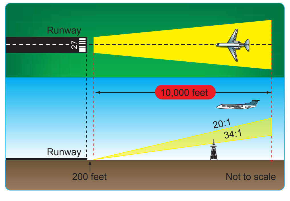
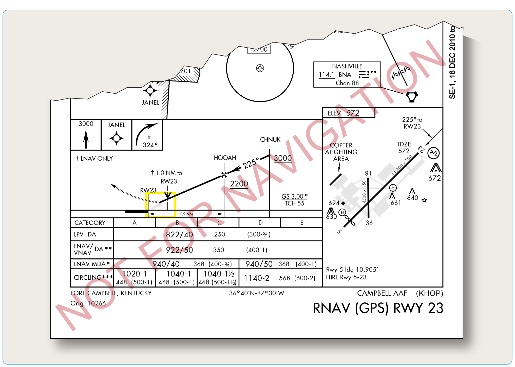
The visibility published on an approach chart is dependent on many variables, including the height above touchdown for straight-in approaches or height above airport elevation for circling approaches. Other factors include the approach light system coverage, and type of approach procedure, such as precision, non-precision, circling or straight-in. Another factor determining the minimum visibility is the penetration of the 34:1 and 20:1 surfaces. These surfaces are inclined planes that begin 200 feet out from the runway and extend outward to the DA point (for approaches with vertical guidance), the VDP location (for non-precision approaches) and 10,000 feet for an evaluation to a circling runway. If there is a penetration of the 34:1 surface, the published visibility can be no lower than three-fourths SM. If there is penetration of the 20:1 surface, the published visibility can be no lower than 1 SM with a note prohibiting approaches to the affected runway at night (both straight-in and circling). [Figure 4-21 ] Circling may be permitted at night if penetrating obstacles are marked and lighted. If the penetrating obstacles are not marked and lighted, a note is published that night circling is “Not Authorized.” Pilots should be aware of these penetrating obstacles when entering the visual and/or circling segments of an approach and take adequate precautions to avoid them. For RNAV approaches only, the presence of a grey shaded line from the MDA to the runway symbol in the profile view is an indication that the visual segment below the MDA is clear of obstructions on the 34:1 slope. Absence of the gray shaded area indicates the 34:1 OCS is not free of obstructions. [Figure 4-22]
Missed Approach
Many reasons exist for executing a missed approach. The primary reasons, of course, are that the required flight visibility prescribed in the IAP being used does not exist when natural vision is used under 14 CFR Part 91, § 91.175c, the required enhanced flight visibility is less than that prescribed in the IAP when an EFVS is used under 14 CFR Part 91, § 91.176, or the required visual references for the runway cannot be seen upon arrival at the DA, DH, or MAP. In addition, according to 14 CFR Part 91, the aircraft must continuously be in a position from which a descent to a landing on the intended runway can be made at a normal rate of descent using normal maneuvers, and for operations conducted under Part 121 or 135, unless that descent rate allows touchdown to occur within the TDZ of the runway of intended landing. CAT II and III approaches call for different visibility requirements as prescribed by the FAA Administrator.
Prior to initiating an instrument approach procedure, the pilot should assess the actions to be taken in the event of a balked (rejected) landing beyond the missed approach point or below the MDA or DA (H) considering the anticipated weather conditions and available aircraft performance. 14 CFR 91.175(e) authorizes the pilot to fly an appropriate missed approach procedure that ensures obstruction clearance, but it does not necessarily consider separation from other air traffic. The pilot must consider other factors such as the aircraft’s geographical location with respect to the prescribed missed approach point, direction of flight, and/ or the minimum turning altitudes in the prescribed missed approach procedure. The pilot must also consider aircraft performance, visual climb restrictions, charted obstacles, published obstacle departure procedure, takeoff visual climb requirements as expressed by nonstandard takeoff minima, other traffic expected to be in the vicinity, or other factors not specifically expressed by the approach procedures.
A clearance for an instrument approach procedure includes a clearance to fly the published missed approach procedure, unless otherwise instructed by ATC. Once descent below the DA, DH, or MDA is begun, a missed approach must be executed if the required visibility is lost or the runway environment is no longer visible, unless the loss of sight of the runway is a result of normal banking of the aircraft during a circling approach. A MAP is also required upon the execution of a rejected landing for any reason, such as men and equipment or animals on the runway, or if the approach becomes unstabilized and a normal landing cannot be performed. After the MAP in the visual segment of a non-precision approach, there may be hazards when executing a missed approach below the MDA. The published missed approach procedure provides obstacle clearance only when the missed approach is conducted on the missed approach segment from or above the missed approach point, and assumes a climb rate of 200 ft/NM or higher, as published. If the aircraft initiates a missed approach at a point other than the missed approach point, from below MDA or DA (H), or on a circling approach, obstacle clearance is not provided by following the published missed approach procedure, nor is separation assured from other air traffic in the vicinity.
The missed approach climb is normally executed at the MAP. If such a climb is initiated at a higher altitude prior to the MAP, pilots must be aware of any published climb-altitude limitations, which must be accounted for when commencing an early climb. Figure 4-23 gives an example of an altitude restriction that would prevent a climb between the FAF and MAP. In this situation, the Orlando Executive ILS or LOC RWY 7 approach altitude is restricted at the BUVAY 3 DME fix to prevent aircraft from penetrating the overlying protected airspace for approach routes into Orlando International Airport. If a missed approach is initiated before reaching BUVAY, a pilot may be required to continue descent to 1,200 feet before proceeding to the MAP and executing the missed approach climb instructions. In addition to the missed approach notes on the chart, the Pilot Briefing Information icons in the profile view indicate the initial vertical and lateral missed approach guidance.
The missed approach course begins at the MAP and continues until the aircraft has reached the designated fix and a holding pattern has been entered. [Figure 4-24] In these circumstances, ATC normally issues further instructions before the aircraft reaches the final fix of the missed approach course. It is also common for the designated fix to be an IAF so that another approach attempt can be made without having to fly from the holding fix to an IAF.
In the event a balked (rejected) landing occurs at a position other than the published missed approach point, the pilot should contact ATC as soon as possible to obtain an amended clearance. If unable to contact ATC for any reason, the pilot should attempt to re−intercept a published segment of the missed approach and comply with route and altitude instructions. If unable to contact ATC, and in the pilot’s judgment it is no longer appropriate to fly the published missed approach procedure, then consider either maintaining visual conditions (if possible) and reattempt a landing, or a circle−climb over the airport. Should a missed approach become necessary when operating to an airport that is not served by an operating control tower, continuous contact with an air traffic facility may not be possible. In this case, the pilot should execute the appropriate go−around/missed approach procedure without delay and contact ATC when able to do so.
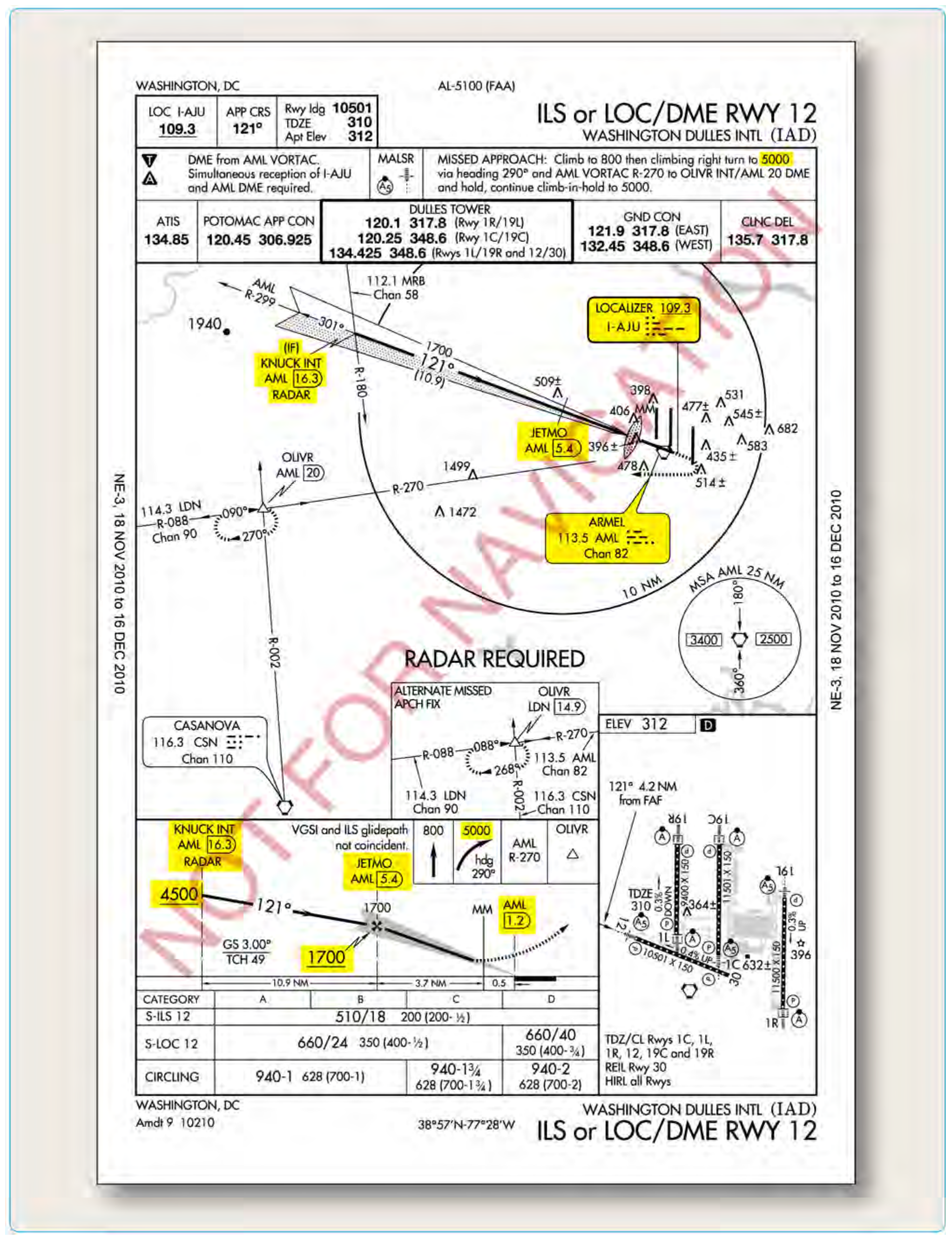
As shown in Figure 4-25, there are many different ways that the MAP can be depicted, depending on the type of approach. On all approach charts, it is depicted in the profile and plan views by the end of the solid course line and the beginning of the dotted missed approach course line for the top-line/ lowest published minima. For a precision approach, the MAP is the point at which the aircraft reaches the DA or DH while on the glideslope/glidepath. MAPs on non-precision approaches can be determined in many different ways. If the primary NAVAID is on the airport, and either a VOR or NDB approach is being executed, the MAP is normally the point at which the aircraft passes the NAVAID.
On some non-precision approaches, the MAP is given as a fixed distance with an associated time from the FAF to the MAP based on the groundspeed of the aircraft. A table on the lower right or left hand side of the approach chart shows the distance in NM from the FAF to the MAP and the time it takes at specific groundspeeds, given in 30 knot increments. Pilots must determine the approximate groundspeed and time based on the approach speed and true airspeed of their aircraft and the current winds along the final approach course. A clock or stopwatch should be started at the FAF of an approach requiring this method. Many non-precision approaches designate a specific fix as the MAP. These can be identified by a course (LOC or VOR) and DME, a cross radial from a VOR, or an RNAV (GPS) waypoint.
Obstacles or terrain in the missed approach segment may require a steeper climb gradient than the standard 200 ft/NM. If a steeper climb gradient is required, a note is published on the approach chart plan view with the penetration description and examples of the required FPM rate of climb for a given groundspeed (future charting uses climb gradient). An alternative is normally charted that allows using the standard climb gradient. [Figure 4-25] In this example, if the missed approach climb requirements cannot be met for the Burbank ILS RWY 8 chart, the alternative is to use the LOC RWY 8 that is charted separately. The LOC RWY 8, S-8 procedure has a MDA that is 400 feet higher than the ILS RWY 8, S-LOC 8 MDA and meets the standard climb gradient requirement over the terrain. For some approaches a new charting standard is requiring two sets of minimums to be published when a climb gradient greater than 200 ft/NM is required. The first set of minimums is the lower of the two, requiring a climb gradient greater than 200 ft/NM. The second set of minimums is higher, but doesn’t require a climb gradient. Shown in Figure 4-26, Barstow-Daggett (KDAG) RNAV (GPS) RWY 26 is an example where there are two LPV lines of minimums.