
Chapter 5
Single-Engine Aircraft Weight and Balance Computations
Introduction
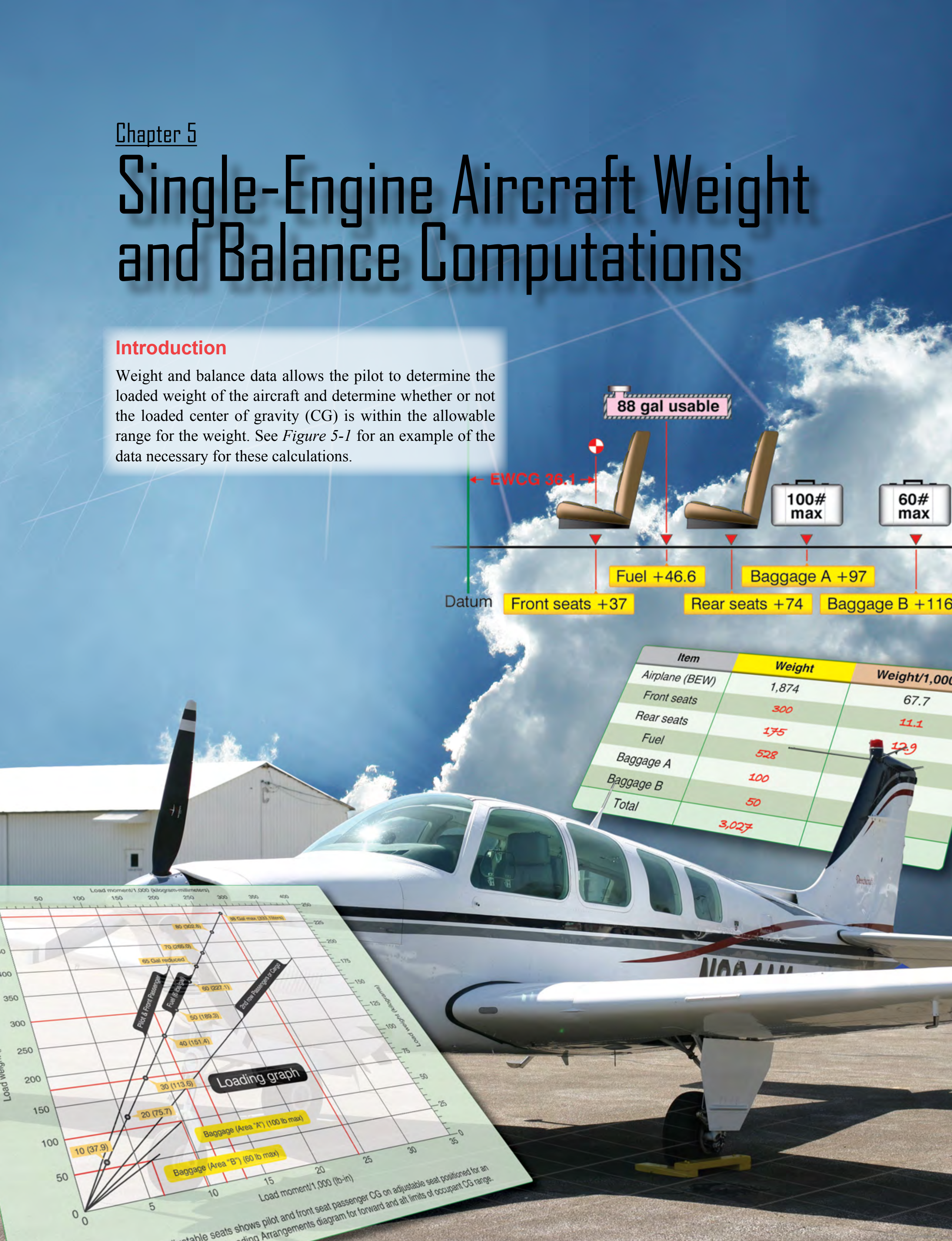
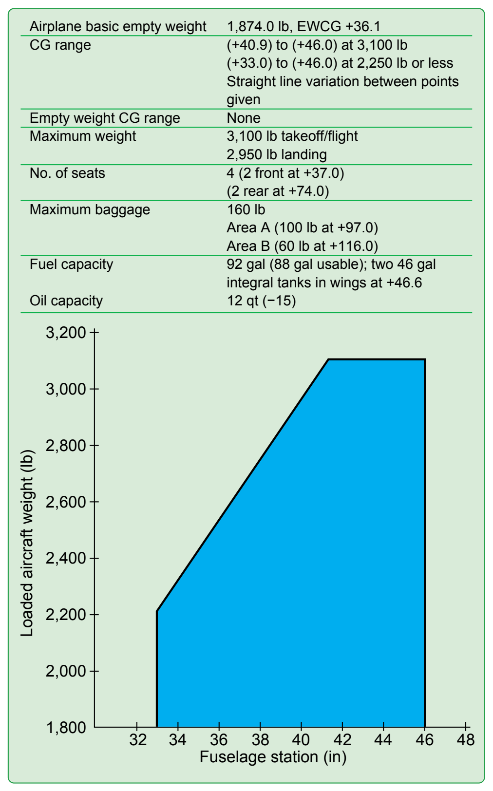
Weight and balance data allows the pilot to determine the loaded weight of the aircraft and determine whether or not the loaded center of gravity (CG) is within the allowable range for the weight. See Figure 5-1 for an example of the data necessary for these calculations.
Determining the Loaded Weight and CG
An important part of preflight planning is determining that the aircraft is loaded so its weight and CG location are within the allowable limits. The methods of accomplishing this are the manual computational method using weights, arms, and moments; the chart method using weight and moment indexes [Figure 5-2]; and the loading graph method, which eliminates the need for some mathematical calculations.
Manual Computational Method
The manual computational method uses weights, arms, and moments. It relates the total weight and CG location to a CG limits chart similar to those included in the Type Certificate Data Sheet (TCDS) and the Pilot’s Operating Handbook/Aircraft Flight Manual (POH/AFM).
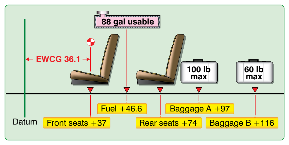
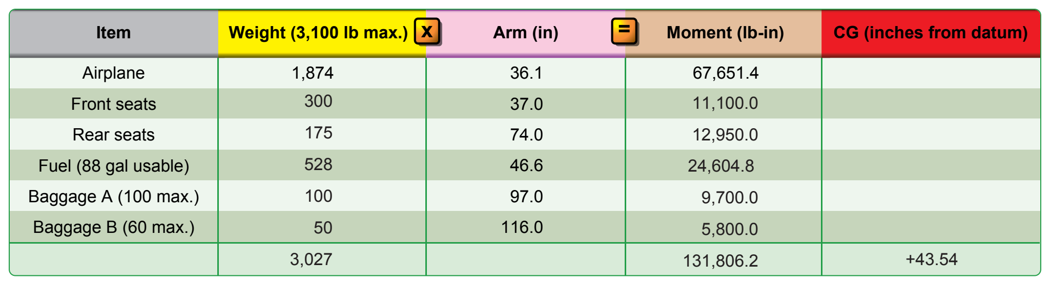
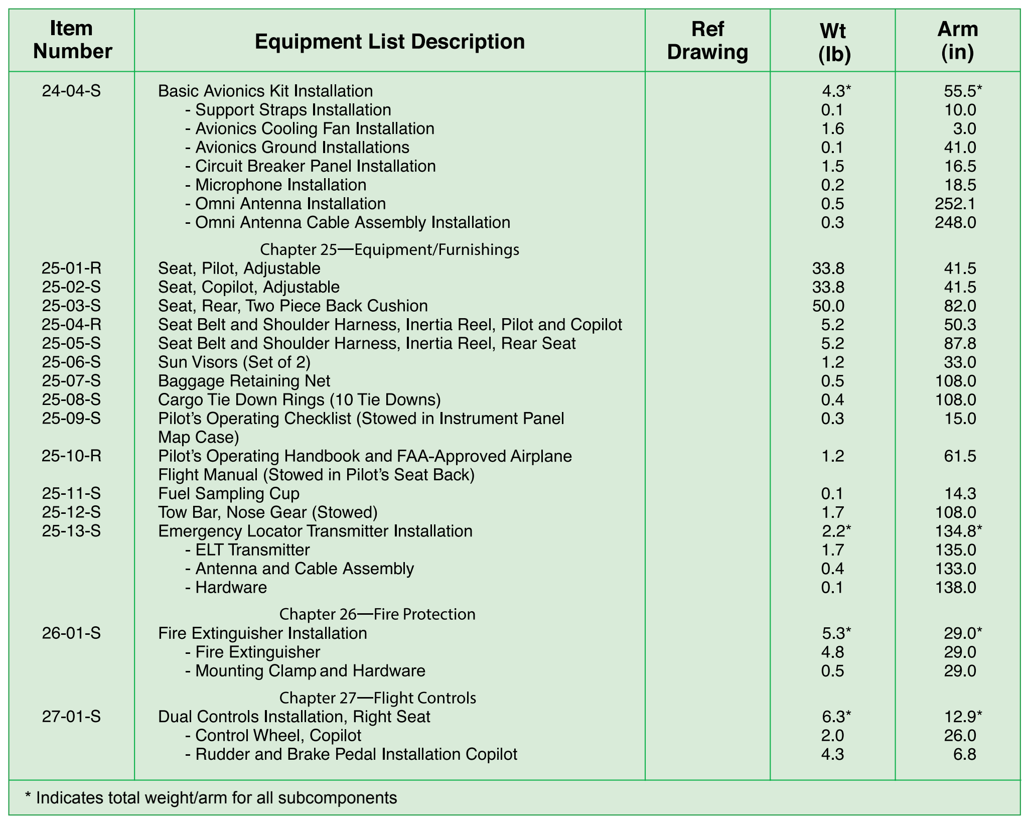
A worksheet, such as the one shown in Figure 5-3, provides a means to record and compute pertinent weights, arms, and moments for all onboard fuel, personnel, equipment, cargo, and baggage that is not included in the aircraft’s basic empty weight (BEW). Figure 5-4 is a sample of a typical equipment list where many of the pertinent weights and moment values can be found.
As part of preflight planning, fill in the blanks in the worksheet with the specific data for the flight. The following weights were used to complete the sample weight and balance worksheet in Figure 5-3.
- Pilot — 120 lb
- Front seat passenger — 180 lb
- Rear seat passenger — 175 lb
- Fuel (88 gal) — 528 lb
- Baggage A — 100 lb
- Baggage B — 50 lb
Multiply each item’s weight by its arm to determine the moment. Then, determine the total weight and the sum of the moments. Divide the total moment by the total weight to determine the CG in inches from the datum. For this example, the total weight is 3,027 pounds and the CG is 43.54 inches aft of the datum (a negative result would have indicated a CG forward of the datum).
To determine whether or not the airplane is properly loaded for this flight, use the CG limits chart. [Figure 5-5] Draw a line vertically upward from the CG of 43.54 inches and one horizontally to the right from the loaded weight of 3,027 pounds. These lines cross inside the envelope, which shows the airplane is properly loaded for takeoff, but 77 pounds overweight for landing. Note that for this sample chart, the envelope is defined by the solid black line that indicates CG limits at or below the maximum weight for takeoff and landing. There is an additional region identified by a segmented black line that includes weights suitable only for takeoff. It is important to note these subtle differences as they may or may not be found in every POH/AFM.

Loading Graph Method
The charts and graphs found in the POH/AFM can help simplify and expedite the preflight weight and balance computation process. Some use a loading graph and moment indexes rather than the arms and moments. These charts eliminate the need for calculating moments and make computations quicker and easier. [Figure 5-6]