
Chapter 6
Multiengine Aircraft Weight and Balance Computations
Use the formula in Figure 6-5 to find the CG in percent MAC.
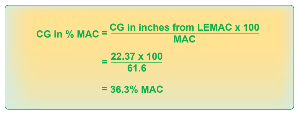
The loaded CG is located at 36.3 percent MAC.
The Chart Method Using Weight and Moment Indexes
As mentioned in the previous chapter, anything that can be done to make careful preflight planning easier makes flying safer. Many manufacturers furnish charts in the Pilot’s Operating Handbook/Aircraft Flight Manual (POH/AFM) that use weight and moment indexes rather than weight, arm, and moments. The charts also help reduce errors by including tables of moment indexes for the various weights.
Consider the loading for this particular flight:
- Cruise fuel flow = 16 gallons per hour
- Estimated time en route = 2 hours, 10 minutes
- Reserve fuel = 45 minutes = 12 gallons
- Total required fuel = 47 gallons
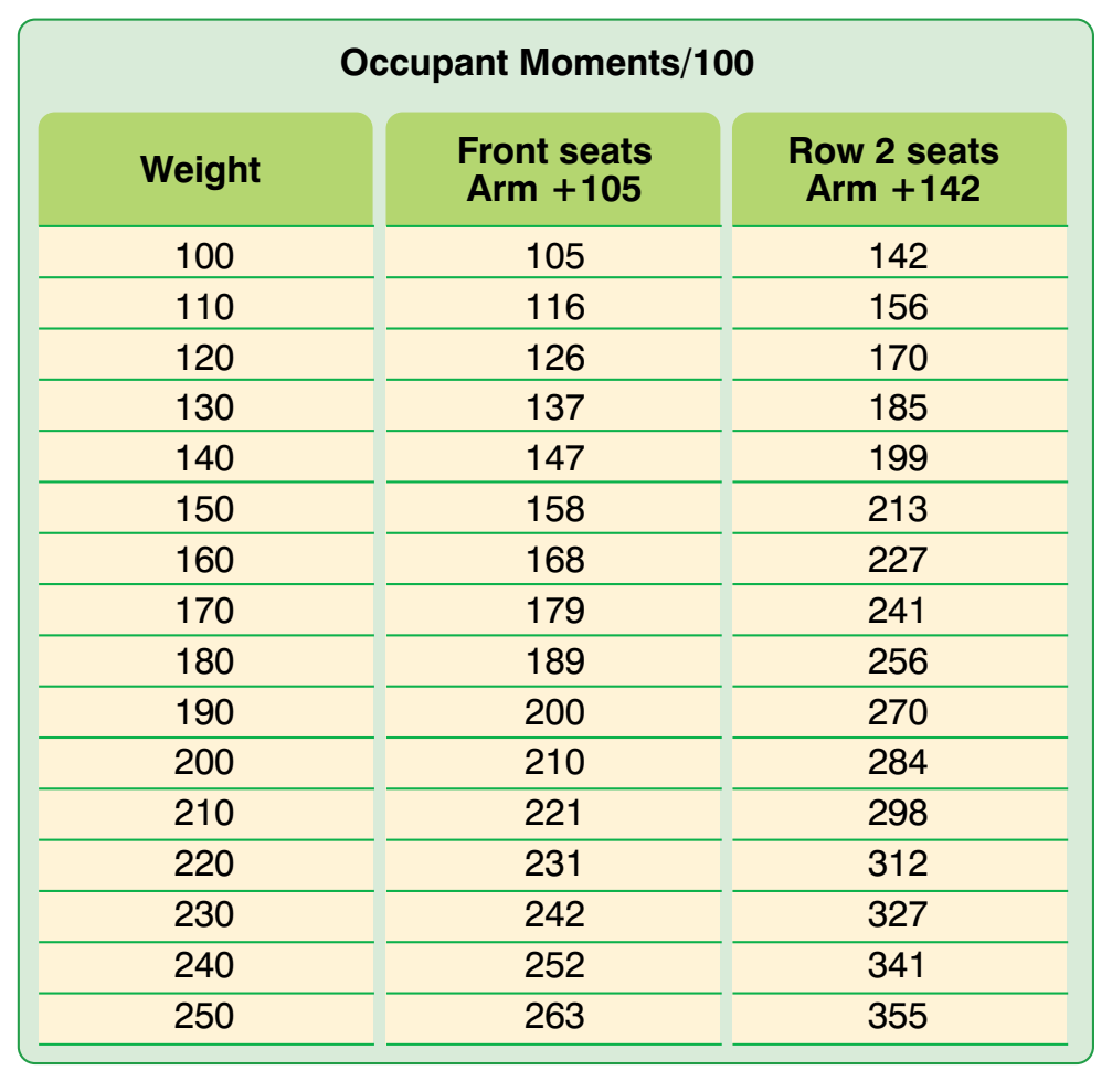
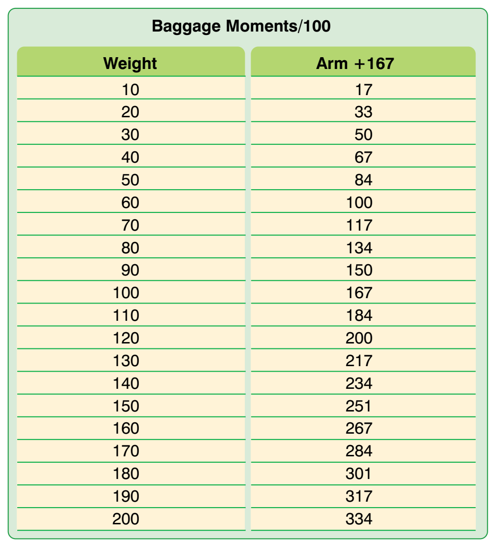
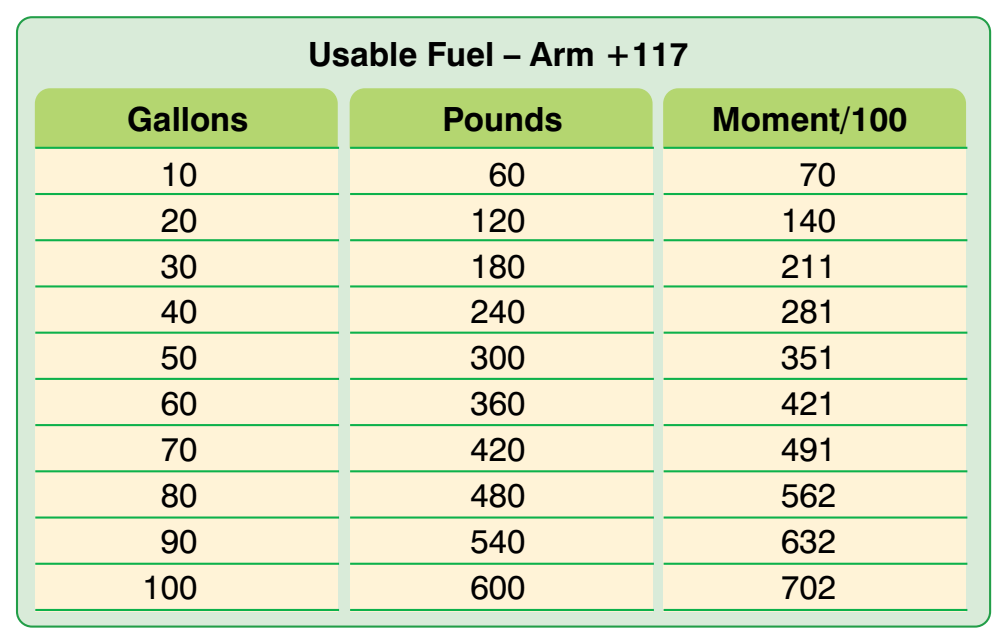
The pilot completes a chart like the one in Figure 6-6 using moment indexes from tables in Figures 6-7 and 6-8.
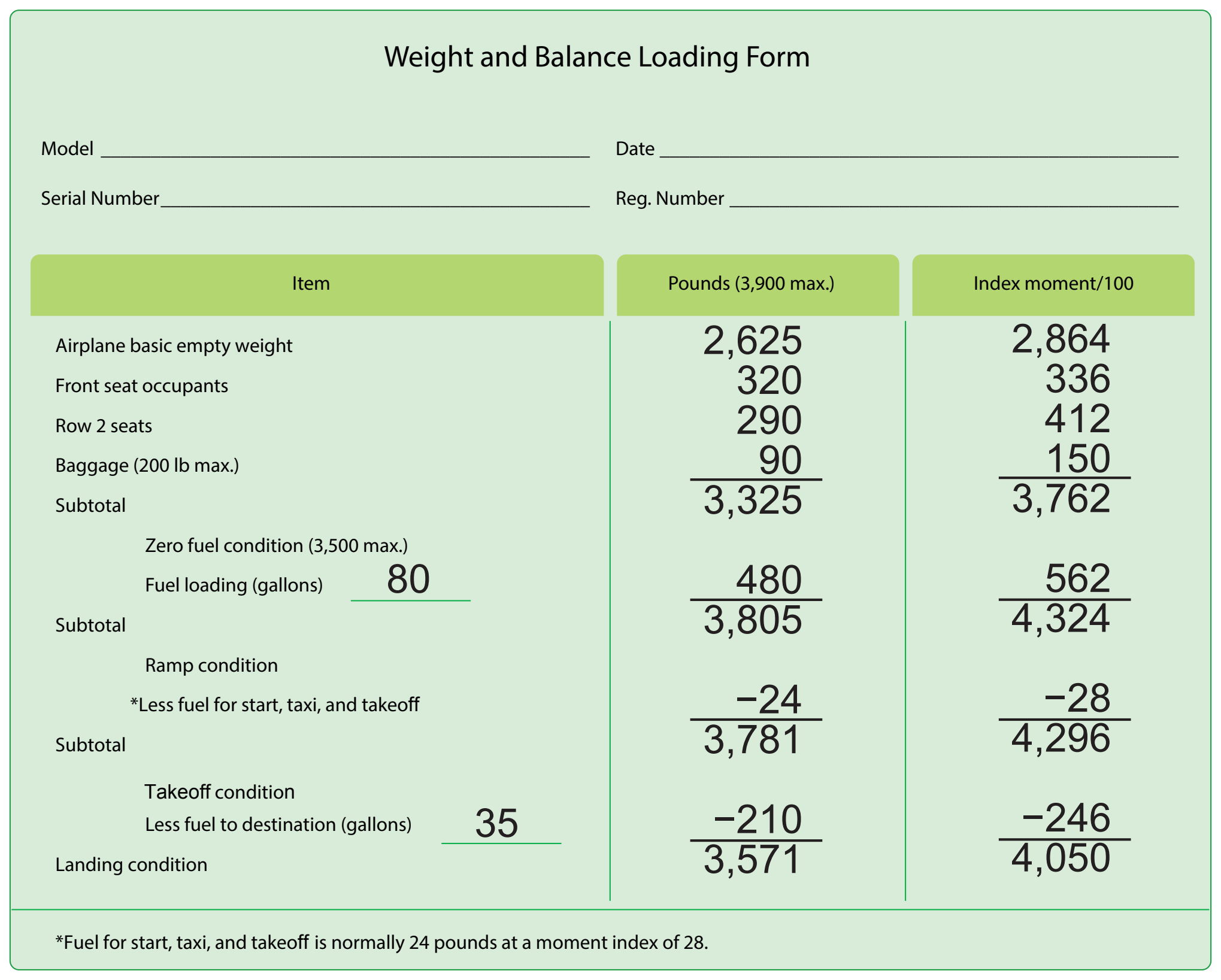
The moments divided by 100 in the index column are found in the charts in Figures 6-7 through 6-9. If the exact weight is not in the chart, interpolate between the weights that are included. When a weight is greater than any of those shown in the charts, add the moment indexes for a combination of weights to get that which is desired. For example, to get the moments divided by 100 for the 320 pounds in the front seats, add the moment index for 100 pounds (105) to that for 220 pounds (231). This gives the moment index of 336 for 320 pounds in the front seats.
Use the moment limits versus weight envelope in Figure 6-10 to determine if the weight and balance conditions are within allowable limits for both takeoff and landing at the destination. The moment limits versus weight envelope is an enclosed area on a graph of three parameters. The diagonal line representing the moment divided by 100 crosses the horizontal line representing the weight at the vertical line representing the CG location in inches aft of the datum. When the lines cross inside the envelope, the aircraft is loaded within its weight and CG limits.
- Takeoff — 3,781 lb and 4,296 moment divided by 100
- Landing — 3,571 lb and 4,050 moment divided by 100
Locate the moment divided by 100 diagonal line for 4,296 and follow it down until it crosses the horizontal line for 3,781 pounds. These lines cross inside the envelope at the vertical line for a CG location of 114 (113.6) inches aft of the datum.
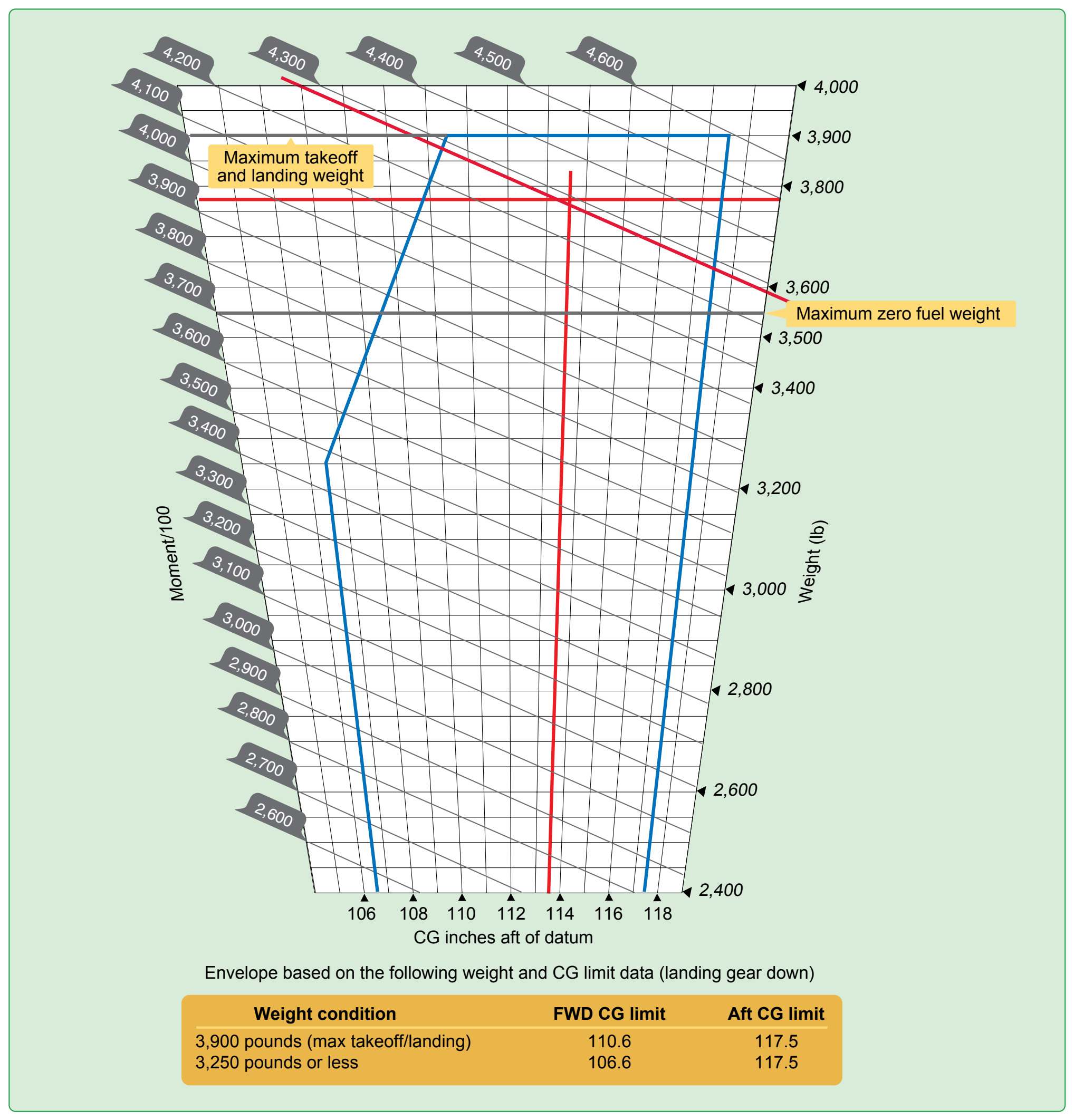
The maximum allowable takeoff weight is 3,900 pounds, and this airplane weighs 3,781 pounds. The CG limits for 3,781 pounds are 109.8 to 117.5. The CG of 114 (113.6) inches falls within these allowable limits.