
Chapter 16
Navigation
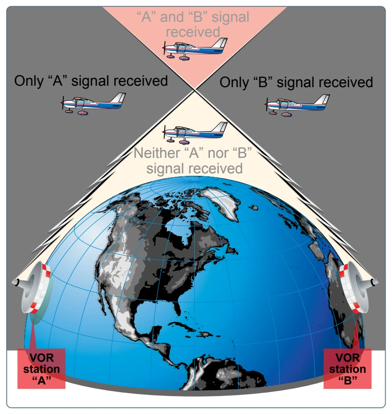
VOR ground stations transmit within a VHF frequency band of 108.0-117.95 MHz. Because the equipment is VHF, the signals transmitted are subject to line-of-sight restrictions. Therefore, its range varies in direct proportion to the altitude of receiving equipment. Generally, the reception range of the signals at an altitude of 1,000 feet above ground level (AGL) is about 40 to 45 miles. This distance increases with altitude. [Figure 16-28]
VORs and VORTACs are classed according to operational use. There are three classes:
- T (Terminal)
- L (Low altitude)
- H (High altitude)
The normal useful range for the various classes is shown in the following table:
The useful range of certain facilities may be less than 50 miles. For further information concerning these restrictions, refer to the Communication/NAVAID Remarks in the Chart Supplement U.S.
The accuracy of course alignment of VOR radials is considered to be excellent. It is generally within plus or minus 1°. However, certain parts of the VOR receiver equipment deteriorate, affecting its accuracy. This is particularly true at great distances from the VOR station. The best assurance of maintaining an accurate VOR receiver is periodic checks and calibrations. VOR accuracy checks are not a regulatory requirement for VFR flight. However, to assure accuracy of the equipment, these checks should be accomplished quite frequently and a complete calibration should be performed each year. The following means are provided for pilots to check VOR accuracy:
- FAA VOR test facility (VOT)
- Certified airborne checkpoints
- Certified ground checkpoints located on airport surfaces
If an aircraft has two VOR receivers installed, a dual VOR receiver check can be made. To accomplish the dual receiver check, a pilot must tune both VOR receivers to the same VOR ground facility. The maximum permissible variation between the two indicated bearings is 4°. A list of the airborne and ground checkpoints is published in the Chart Supplement U.S.
Basically, these checks consist of verifying that the VOR radials the aircraft equipment receives are aligned with the radials the station transmits. There are not specific tolerances in VOR checks required for VFR flight. But as a guide to assure acceptable accuracy, the required IFR tolerances can be used-±4° for ground checks and ±6° for airborne checks. These checks can be performed by the pilot.
The VOR transmitting station can be positively identified by its Morse code identification or by a recorded voice identification that states the name of the station followed by “VOR.” Many FSSs transmit voice messages on the same frequency that the VOR operates. Voice transmissions should not be relied upon to identify stations because many FSSs remotely transmit over several omniranges that have names different from that of the transmitting FSS. If the VOR is out of service for maintenance, the coded identification is removed and not transmitted. This serves to alert pilots that this station should not be used for navigation. VOR receivers are designed with an alarm flag to indicate when signal strength is inadequate to operate the navigational equipment. This happens if the aircraft is too far from the VOR or the aircraft is too low and, therefore, is out of the line of sight of the transmitting signals.
Using the VOR
In review, for VOR radio navigation, there are two components required: ground transmitter and aircraft receiving equipment. The ground transmitter is located at a specific position on the ground and transmits on an assigned frequency. The aircraft equipment includes a receiver with a tuning device and a VOR or omninavigation instrument. The navigation instrument could be a course deviation indicator (CDI), horizontal situation indicator (HSI), or a radio magnetic indicator (RMI). Each of these instruments indicates the course to the tuned VOR.
Course Deviation Indicator (CDI)
The CDI is found in most training aircraft. It consists of an omnibearing selector (OBS) sometimes referred to as the course selector, a CDI needle (left-right needle), and a TO/ FROM indicator.
The course selector is an azimuth dial that can be rotated to select a desired radial or to determine the radial over which the aircraft is flying. In addition, the magnetic course “TO” or “FROM” the station can be determined.
When the course selector is rotated, it moves the CDI or needle to indicate the position of the radial relative to the aircraft. If the course selector is rotated until the deviation needle is centered, the radial (magnetic course “FROM” the station) or its reciprocal (magnetic course “TO” the station) can be determined. The course deviation needle also moves to the right or left if the aircraft is flown or drifting away from the radial which is set in the course selector.
By centering the needle, the course selector indicates either the course “FROM” the station or the course “TO” the station. If the flag displays a “TO,” the course shown on the course selector must be flown to the station. [Figure 16-29] If “FROM” is displayed and the course shown is followed, the aircraft is flown away from the station.