
Chapter 16
Navigation
Charting the Course
Once the weather has been checked and some preliminary planning completed, it is time to chart the course and determine the data needed to accomplish the flight. The following sections provide a logical sequence to follow in charting the course, complete a flight log, and filing a flight plan. In the following example, a trip is planned based on the following data and the sectional chart excerpt in Figure 16-25.
Route of flight: Chickasha Airport direct to Guthrie Airport True airspeed (TAS)........................................115 knots Winds aloft...........................................360° at 10 knots Usable fuel.....................................................38 gallons Fuel rate...............................................................8 GPH Deviation..................................................................+2°
Steps in Charting the Course
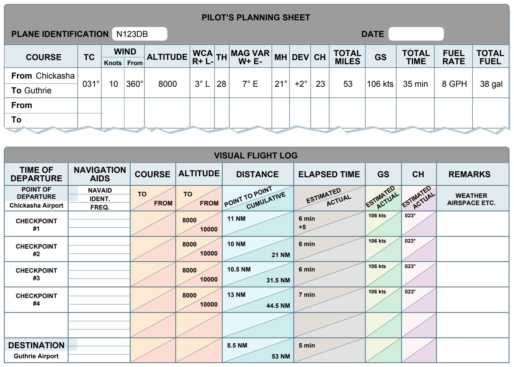
The following is a suggested sequence for arriving at the pertinent information for the trip. As information is determined, it may be noted as illustrated in the example of a flight log in
use a mathematical formula or a manual or electronic flight computer. If unfamiliar with the use of a manual or electronic computer, it would be advantageous to read the operation manual and work several practice problems at this point.
First, draw a line from Chickasha Airport (point A) directly to Guthrie Airport (point F). The course line should begin at the center of the airport of departure and end at the center of the destination airport. If the route is direct, the course line consists of a single straight line. If the route is not direct, it consists of two or more straight line segments. For example, a VOR station that is off the direct route, but makes navigating easier, may be chosen (radio navigation is discussed later in this chapter).
Appropriate checkpoints should be selected along the route and noted in some way. These should be easy-to-locate points, such as large towns, large lakes and rivers, or combinations of recognizable points, such as towns with an airport, towns with a network of highways, and railroads entering and departing.
Normally, choose only towns indicated by splashes of yellow on the chart. Do not choose towns represented by a small circle-these may turn out to be only a half-dozen houses. (In isolated areas, however, towns represented by a small circle can be prominent checkpoints.) For this trip, four checkpoints have been selected. Checkpoint 1 consists of a tower located east of the course and can be further identified by the highway and railroad track, which almost parallels the course at this point. Checkpoint 2 is the obstruction just to the west of the course and can be further identified by Will Rogers World Airport, which is directly to the east. Checkpoint 3 is Wiley Post Airport, which the aircraft should fly directly over. Checkpoint 4 is a private, non-surfaced airport to the west of the course and can be further identified by the railroad track and highway to the east of the course.
The course and areas on either side of the planned route should be checked to determine if there is any type of airspace with which the pilot should be concerned or which has special operational requirements. For this trip, it should be noted that the course passes through a segment of the Class C airspace surrounding Will Rogers World Airport where the floor of the airspace is 2,500 feet mean sea level (MSL) and the ceiling is 5,300 feet MSL (point B). Also, there is Class D airspace from the surface to 3,800 feet MSL surrounding Wiley Post Airport (point C) during the time the control tower is in operation.
Study the terrain and obstructions along the route. This is necessary to determine the highest and lowest elevations, as well as the highest obstruction to be encountered so an appropriate altitude that conforms to 14 CFR part 91 regulations can be selected. If the flight is to be flown at an altitude of more than 3,000 feet above the terrain, conformance to the cruising altitude appropriate to the direction of flight is required. Check the route for particularly rugged terrain so it can be avoided. Areas where a takeoff or landing is made should be carefully checked for tall obstructions. Television transmitting towers may extend to altitudes over 1,500 feet above the surrounding terrain. It is essential that pilots be aware of their presence and location. For this trip, it should be noted that the tallest obstruction is
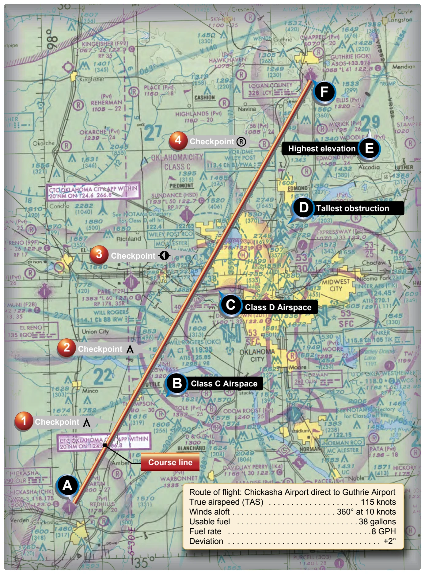
part of a series of antennas with a height of 2,749 feet MSL (point D). The highest elevation should be located in the northeast quadrant and is 2,900 feet MSL (point E).
Since the wind is no factor and it is desirable and within the aircraft’s capability to fly above the Class C and D airspace to be encountered, an altitude of 5,500 feet MSL is chosen. This altitude also gives adequate clearance of all obstructions, as well as conforms to the 14 CFR part 91 requirement to fly at an altitude of odd thousand plus 500 feet when on a magnetic course between 0 and 179°.
Next, the pilot should measure the total distance of the course, as well as the distance between checkpoints. The total distance is 53 NM, and the distance between checkpoints is as noted on the flight log in Figure 16-26.
After determining the distance, the TC should be measured. If using a plotter, follow the directions on the plotter. The TC is 031°. Once the TH is established, the pilot can determine the compass heading. This is done by following the formula given earlier in this chapter.
The formula is:
TC ± WCA = TH ± V = MH ± D = CH
The WCA can be determined by using a manual or electronic flight computer. Using a wind of 360° at 10 knots, it is determined the WCA is 3° left. This is subtracted from the TC making the TH 28°. Next, the pilot should locate the isogonic line closest to the route of the flight to determine variation. Figure 16-25 shows the variation to be 6.30° E (rounded to 7° E), which means it should be subtracted from the TH, giving an MH of 21°. Next, add 2° to the MH for the deviation correction. This gives the pilot the compass heading of 23°.