
Chapter 7
Aircraft Systems
A pilot flying an aircraft with a turbocharger should be aware of system limitations. For example, a turbocharger turbine and impeller can operate at rotational speeds in excess of 80,000 rpm while at extremely high temperatures. To achieve high rotational speed, the bearings within the system must be constantly supplied with engine oil to reduce the frictional forces and high temperature. To obtain adequate lubrication, the oil temperature should be in the normal operating range before high throttle settings are applied. In addition, allow the turbocharger to cool and the turbine to slow down before shutting the engine down. Otherwise, the oil remaining in the bearing housing will boil, causing hard carbon deposits to form on the bearings and shaft. These deposits rapidly deteriorate the turbocharger’s efficiency and service life. For further limitations, refer to the AFM/POH.
High Altitude Performance
As an aircraft equipped with a turbocharging system climbs, the waste gate is gradually closed to maintain the maximum allowable manifold pressure. At some point, the waste gate is fully closed and further increases in altitude cause the manifold pressure to decrease. This is the critical altitude, which is established by the aircraft or engine manufacturer. When evaluating the performance of the turbocharging system, be aware that if the manifold pressure begins decreasing before the specified critical altitude, the engine and turbocharging system should be inspected by a qualified aviation maintenance technician (AMT) to verify that the system is operating properly.
Ignition System
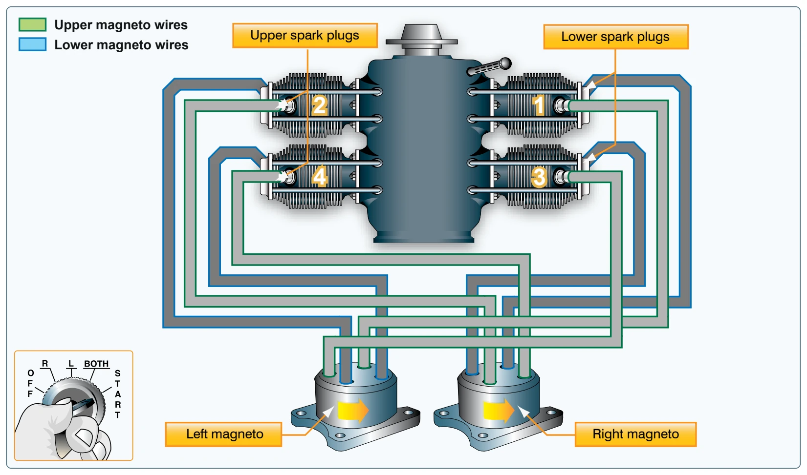
In a spark ignition engine, the ignition system provides a spark that ignites the fuel-air mixture in the cylinders and is made up of magnetos, spark plugs, high-tension leads, and an ignition switch. [Figure 7-16]
A magneto uses a permanent magnet to generate an electrical current completely independent of the aircraft’s electrical system. The magneto generates sufficiently high voltage to jump a spark across the spark plug gap in each cylinder. The system begins to fire when the starter is engaged and the crankshaft begins to turn. It continues to operate whenever the crankshaft is rotating.
Most standard certificated aircraft incorporate a dual ignition system with two individual magnetos, separate sets of wires, and spark plugs to increase reliability of the ignition system. Each magneto operates independently to fire one of the two spark plugs in each cylinder. The firing of two spark plugs improves combustion of the fuel-air mixture and results in a slightly higher power output. If one of the magnetos fails, the other is unaffected. The engine continues to operate normally, although a slight decrease in engine power can be expected. The same is true if one of the two spark plugs in a cylinder fails.
The operation of the magneto is controlled in the flight deck by the ignition switch. The switch has five positions:
- OFF
- R (right)
- L (left)
- BOTH
- START
With RIGHT or LEFT selected, only the associated magneto is activated. The system operates on both magnetos when BOTH is selected.
A malfunctioning ignition system can be identified during the pretakeoff check by observing the decrease in rpm that occurs when the ignition switch is first moved from BOTH to RIGHT and then from BOTH to LEFT. A small decrease in engine rpm is normal during this check. The permissible decrease is listed in the AFM or POH. If the engine stops running when switched to one magneto or if the rpm drop exceeds the allowable limit, do not fly the aircraft until the problem is corrected. The cause could be fouled plugs,
broken or shorted wires between the magneto and the plugs, or improperly timed firing of the plugs. It should be noted that “no drop” in rpm is not normal, and in that instance, the aircraft should not be flown.
Following engine shutdown, turn the ignition switch to the OFF position. Even with the battery and master switches OFF, the engine can fire and turn over if the ignition switch is left ON and the propeller is moved because the magneto requires no outside source of electrical power. Be aware of the potential for serious injury in this situation.
Even with the ignition switch in the OFF position, if the ground wire between the magneto and the ignition switch becomes disconnected or broken, the engine could accidentally start if the propeller is moved with residual fuel in the cylinder. If this occurs, the only way to stop the engine is to move the mixture lever to the idle cutoff position, then have the system checked by a qualified AMT.
Oil Systems
The engine oil system performs several important functions:
- Lubrication of the engine’s moving parts
- Cooling of the engine by reducing friction
- Removing heat from the cylinders
- Providing a seal between the cylinder walls and pistons
- Carrying away contaminants
Reciprocating engines use either a wet-sump or a dry-sump oil system. In a wet-sump system, the oil is located in a sump that is an integral part of the engine. In a dry-sump system, the oil is contained in a separate tank and circulated through the engine by pumps. [Figure 7-17]
The main component of a wet-sump system is the oil pump, which draws oil from the sump and routes it to the engine. After the oil passes through the engine, it returns to the sump. In some engines, additional lubrication is supplied by the rotating crankshaft, which splashes oil onto portions of the engine.