User-friendly explanations of instrument approach charts, planviews, profiles, minimums, airport diagrams, departures, arrivals, and visual procedures.
Copter DPs may also include a visual or VFR segment. Visual segments are depicted using the dashed line symbol below.
Visual Flight Segment
Visual Flight Segment — source page 124.
Runway Construction Paved or hard surfaced runways consisting of concrete, asphalt, bitumen, or macadam are shown in solid color. Metal surfaced runways are shown using a solid color crosshatch pattern. Ultralight areas, ski landing areas, unpaved or runway other than hard surface, such as sod, clay, gravel, etc., is shown using a solid color dot pattern. Further details regarding runway surface and surface treatment can be found in the Chart Supplement. Runway construction is depicted as follows: Hard Surface Other Than Hard Surface Metal Surface Closed Runway Under Construction Taxiways, Parking Areas Displaced Threshold Closed Pavement Water Runway Stopways, Overruns, Blast Pads Hot Spots Hot Spots (HS) are a runway safety related problem area or intersection on an airport. Typically it is a complex or confusing taxiway/taxiway or taxiway/runway intersection. A confusing condition may be compounded by a miscommunication between a controller and a pilot, and may cause an aircraft separation standard to be compromised. The area may have a history of surface incidents or the potential for surface incidents. Hot Spots are indicated on the Airport Diagram with a brown open circle or ellipse leadered to a Hot Spot number, e.g., HS 1. The number corresponds to a listing and description on the Hot Spot page in the front the TPP. More information and the location of Hot Spots can be found at https://www.faa.gov/air_traffic/flight_info/aeronav/digital_products/dtpp/search/. DEPARTURE PROCEDURES (DPs) Departure Procedures (DPs) are designed specifically to assist pilots in avoiding obstacles during the climb to the minimum enroute altitude, and/or airports that have civil IFR takeoff minimums other than standard. There are two types of DPs: Obstacle Departure Procedures (ODPs), printed either textually or graphically and Standard Instrument Departures (SIDs), always printed graphically. SIDs are primarily designed for system enhancement and to reduce pilot/controller workload, and require ATC clearance. ODPs provide obstruction clearance via the least onerous route from the terminal area and may be flown without ATC clearance. All DPs provide the pilot with a safe departure from the airport and transition to the enroute structure. Generally, DP charts are depicted “not to scale” due to the great distances involved on some procedures or route segments. A “to scale” portrayal may be used if readability is assured. The DP will show the departure routing, including transitions to the appropriate enroute structure. All routes, turns, altitudes, NAVAIDs, facilities forming intersections and fixes, and those facilities terminating the departure route are shown. A textual description of the departure procedure is also provided. For RNAV DPs, the transition text consists of the transition name and associated computer code. On non-RNAV DPs, the transition text will also include the description of all turns, altitudes, radials, bearings and facilities/fixes needed to guide the user from the common departure point to the terminating facility fix. Copter DPs may also include a visual or VFR segment. Visual segments are depicted using the dashed line symbol below. Visual Flight Segment
Source page 125
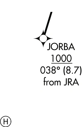
VFR Segments are not depicted with a line, but include the reference bearing and distance information at the endpoint of the VFR Segment, when provided, as shown below.
Example of Copter with VFR Segment
Copter with VFR Segment example showing endpoint reference bearing and distance — source page 125.
Initial Climb Area (ICA)
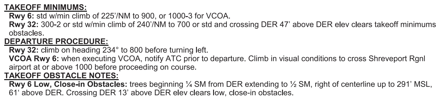
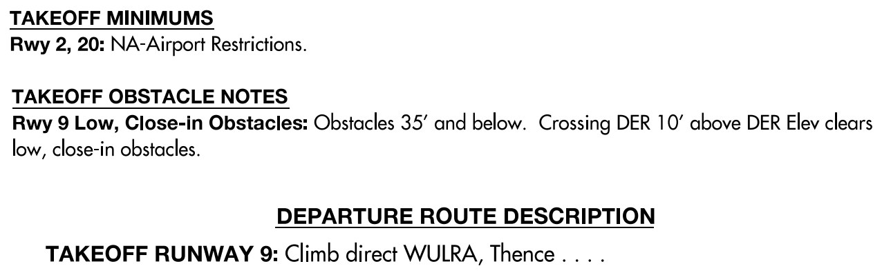
The FAA has redefined the ICA criteria used to evaluate and identify the obstacles that penetrate the 40:1 obstacle clearance surface. To ensure the pilot knows which evaluation was applied, the charting will be different by bolding certain headers and runway information on Textual and Graphic Departure Procedures to indicate the new ICA criteria has been used. (See Charting Notice 26-03).
STARs are pre-planned Instrument Flight Rule (IFR) air traffic control arrival procedures for pilot use in graphic and/or textual form. STARs depict prescribed routes to transition the aircraft from the enroute structure to a fix in the terminal area from which an instrument approach can be conducted. STARs reduce pilot/controller workload and air-ground communications, minimizing error potential in delivery and receipt of clearances.
STAR charts generally shall be depicted ‘not to scale’ due to the great distances involved on many procedures and route segments. A ‘to scale’ depiction may be used only if readability is assured.
The STAR will show the arrival routing, including transitions from the appropriate enroute structure. All routes, turns, altitudes, NAVAIDs, facilities forming intersections and fixes, and those facilities/fixes terminating or beginning the arrival route shall be shown in the graphic depiction. A textual description of the arrival procedure is also provided. For RNAV STARs, transition text will consist of the transition name and associated computer code. For non-RNAV STARs, the transition text will also include a description of all turns, altitudes, radials, bearings and facilities/fixes needed to guide the user from the entry point to the common facility/fix.
VFR Segments are not depicted with a line, but include the reference bearing and distance information at the endpoint of the VFR Segment, when provided, as shown below. Example of Copter with VFR Segment Initial Climb Area (ICA) The FAA has redefined the ICA criteria used to evaluate and identify the obstacles that penetrate the 40:1 obstacle clearance surface. To ensure the pilot knows which evaluation was applied, the charting will be different by bolding certain headers and runway information on Textual and Graphic Departure Procedures to indicate the new ICA criteria has been used. (See Charting Notice 26-03). Textual Departure Procedures: Graphic Departure Procedures: STANDARD TERMINAL ARRIVAL (STARs) CHARTS STARs are pre-planned Instrument Flight Rule (IFR) air traffic control arrival procedures for pilot use in graphic and/or textual form. STARs depict prescribed routes to transition the aircraft from the enroute structure to a fix in the terminal area from which an instrument approach can be conducted. STARs reduce pilot/controller workload and air-ground communications, minimizing error potential in delivery and receipt of clearances. STAR charts generally shall be depicted ‘not to scale’ due to the great distances involved on many procedures and route segments. A ‘to scale’ depiction may be used only if readability is assured. The STAR will show the arrival routing, including transitions from the appropriate enroute structure. All routes, turns, altitudes, NAVAIDs, facilities forming intersections and fixes, and those facilities/fixes terminating or beginning the arrival route shall be shown in the graphic depiction. A textual description of the arrival procedure is also provided. For RNAV STARs, transition text will consist of the transition name and associated computer code. For non-RNAV STARs, the transition text will also include a description of all turns, altitudes, radials, bearings and facilities/fixes needed to guide the user from the entry point to the common facility/fix.
Source page 126
Cookie Preferences
We use cookies to operate this website, improve performance, understand site traffic, and personalize your experience. Essential cookies are always active because they are required for the website to function.
Required for basic site functionality and security.
Help us understand how visitors use the website so we can improve it.
May be used for advertising, remarketing, or social media features.
You can update your choices anytime using Cookie Settings. View Privacy Policy