User-friendly explanations of instrument approach charts, planviews, profiles, minimums, airport diagrams, departures, arrivals, and visual procedures.
Source page 122
Airport Elevation and Touchdown Zone Elevation
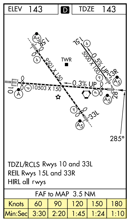
The airport elevation is shown enclosed within a box in the upper left corner of the sketch box and the touchdown zone elevation (TDZE) is shown in the upper right corner of the sketch box. The airport elevation is the highest point of an airport’s usable runways measured in feet from mean sea level. The TDZE is the highest elevation in the first 3,000 feet of the landing surface. Circling only approaches will not show a TDZE.
Runway Declared Distance Information
Runway declared distance information when available will be indicated by and is shown to the right of the airport elevation in the sketch box. Declared distances for a runway represent the maximum distances available and suitable for meeting takeoff and landing distance performance requirements.
Runway-declared-distance-information symbol — black D — source page 122.
Runway Lights
Airport sketch with runway-lighting notes and FAF-to-MAP time/distance table — TDZL/RCLS RWYs 10/33L, REIL RWYs 15L/33R, HIRL all runways — source page 122.
Notes regarding approach lighting systems are shown at the bottom of the sketch box. Runway lights (HIRL) (MIRL) (LIRL) (TDZL) (TDZL/RCLS) shall be indicated by a note, e.g. HIRL Rwy 9-27. Pilot capability to acitvate the airport lighting is shown using a symbol.
Black L symbol indicating pilot-controlled airport lighting — source page 122.
Other approach lighting is shown on the airport sketch as a symbol on the side of the runway where they are actually located. Symbols that are shown in negative indicate pilot-controlled lighting.
Runway centerline lights (RCLS) are installed on some precision approach runways to facilitate landing under adverse visibility conditions. They are located along the runway centerline and are spaced at 50 foot intervals. Runways with RCLS are shown in a negative dot pattern through the middle of the solid runway as illustrated in the airport sketch to right.
Runway centerline lights will be indicated by a note only when pilot controlled or when paired with TDZL, e.g., TDZL/RCLS Rwys 10 and 33L.
Time/Distance Table
When applicable, a Time/Distance Table is provided below the airport sketch. The table provides the distance and time that is required from the final approach fix to the missed approach point for select groundspeeds.
Base Information (Copter Approaches Only)
Base Information, as required and necessary to identify the MAP area and in the vicinity of the landing area shall be provided. Information shall be limited to and depict significant visual landmark features at and surrounding the MAP area and the heliport/pad of intended landing.
AIRPORT DIAGRAMS
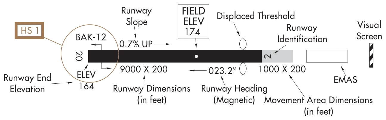
Airport Diagrams are specifically designed to assist in the movement of ground traffic at locations with complex runway/taxiway configurations. Airport Diagrams are not intended for use in approach and landing or departure operations. An airport diagram assists pilots in identifying their location on the airport, thus reducing requests for “progressive taxi instructions” from controllers.
Annotated airport-diagram runway features — hot spot, slope/elevations/dimensions/heading, displaced threshold, runway ID, EMAS, visual screen — source page 122.
Cookie Preferences
We use cookies to operate this website, improve performance, understand site traffic, and personalize your experience. Essential cookies are always active because they are required for the website to function.
Required for basic site functionality and security.
Help us understand how visitors use the website so we can improve it.
May be used for advertising, remarketing, or social media features.
You can update your choices anytime using Cookie Settings. View Privacy Policy