Responsive VFR Sectional and Terminal Area Chart legends for airports, radio aids, airspace, procedures, culture, hydrography, and relief.
Airspace beginning at the surface with an airspace exclusion area where Class E airspace is excluded below 1200’ MSL.
AIRSPACE INFORMATION (Continued) Class C Airspace Appropriate notes as required may be shown. (Mode C see FAR 91.215/ AIM) Class E Airspace The limits of Class E airspace shall be shown by narrow vignettes or by the dashed magenta symbol. Individual units of designated airspace are not necessarily shown; instead, the aggregate lateral and vertical limits shall be defined by the following: Airspace beginning at the surface designated for airports and extension areas. Airspace beginning at 700 feet AGL that laterally abuts 1200 feet or higher Class E Airspace. Airspace beginning at 700 feet AGL that laterally abuts uncontrolled (Class G) airspace. Airspace beginning at 1200 feet AGL that laterally abuts uncontrolled (Class G) airspace. Differentiates floors of airspace greater than 700 feet above the surface. When the ceiling is less than 18,000 feet MSL, the value prefixed by the word “CEILING”, shall be shown along the limits. Class D Airspace Altitude in hundreds of feet MSL (A minus in front of the figure is used to indicate “from surface to but not including...”) Airspace beginning at the surface designated for airports and extension areas. Airspace beginning at the surface with an airspace exclusion area where Class E airspace is excluded below 1200’ MSL.
Source page 28
AIRSPACE INFORMATION (Continued)
Class E Airspace (Continued)
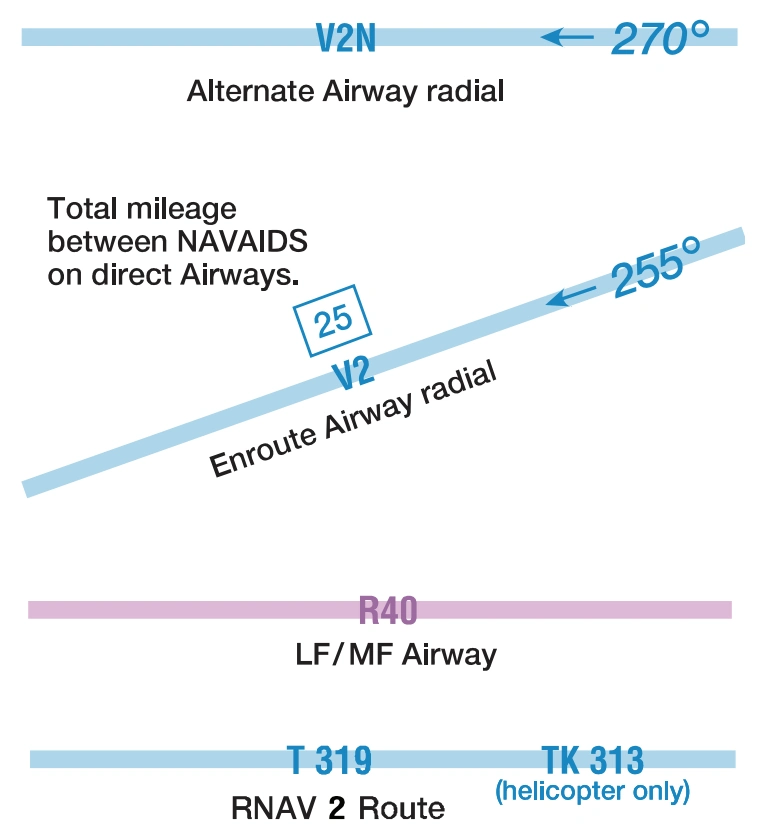
Low Altitude Airways VOR and LF/MF (Class E Airspace)
Low altitude Federal Airways are indicated by centerline.
Only the controlled airspace effective below 18,000 feet MSL is shown
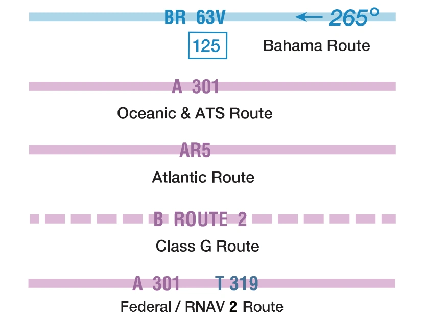
Miscellaneous Air Routes
Combined Federal Airway/RNAV 2 “T” Routes are identified in solid blue type adjacent to the solid magenta federal airway identification.
The joint route symbol is screened magenta.
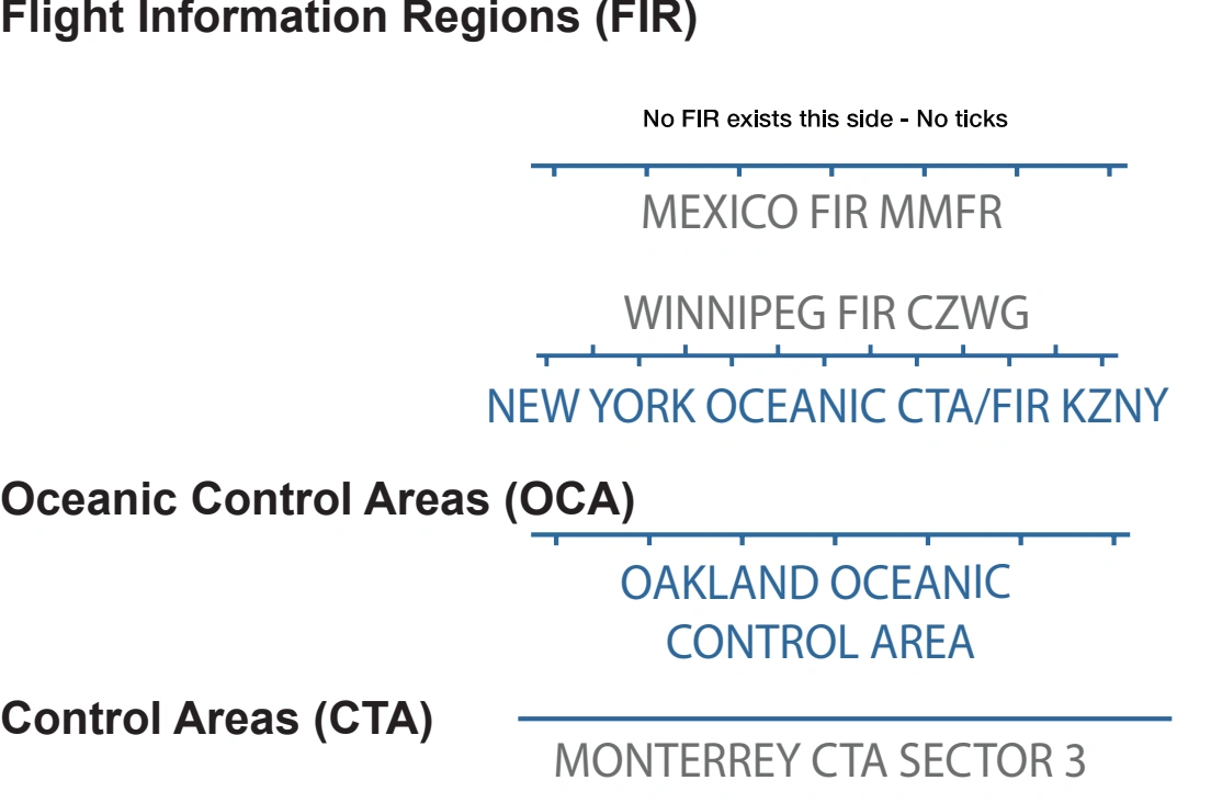
Flight Information Regions (FIR)
Flight Information Regions (FIR), Oceanic Control Areas (OCA), and Control Areas (CTA) boundary examples — source page 28.
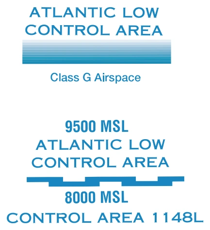
Offshore-control-area labels and vertical limits — Atlantic Low / Control Area 1148L — source page 28.
Foreign/offshore limited-chart-information note — source page 28.
Cookie Preferences
We use cookies to operate this website, improve performance, understand site traffic, and personalize your experience. Essential cookies are always active because they are required for the website to function.
Required for basic site functionality and security.
Help us understand how visitors use the website so we can improve it.
May be used for advertising, remarketing, or social media features.
You can update your choices anytime using Cookie Settings. View Privacy Policy