Chapter 12
Transition to Complex Airplanes
Since the recommendations given in the AFM/POH are based on the airplane and the flap design, the pilot should relate the manufacturer’s recommendation to aerodynamic effects of flaps. This requires basic background knowledge of flap aerodynamics and geometry. With this information, a decision as to the degree of flap deflection and time of deflection based on runway and approach conditions relative to the wind conditions can be made.
The time of flap extension and the degree of deflection are related. Large changes in flap deflection at one single point in the landing pattern can produce large lift changes that require significant pitch and power changes in order to maintain airspeed and descent angle. Consequently, there is an advantage to extending flaps in increments while in the landing pattern. Incremental deflection of flaps on downwind, base leg, and final approach allow smaller adjustments of pitch and power and support a stabilized approach.
While normal, soft-field, or short-field landings require minimal speed at touchdown, a short-field obstacle approach requires minimum speed and a steep approach angle. Flap extension, particularly beyond 30°, results in significant levels of drag. The drag can produce a high sink rate that the pilot needs to control with power. When a pilot uses power during a steep approach or short-field approach to offset the drag produced by the flaps, the landing flare becomes critical. A reduction in power too early can result in a hard landing, airplane damage, or loss of control. A reduction in power too late causes the airplane to float down the runway.
Crosswind component is another factor to be considered in the degree of flap extension. The deflected flap presents a surface area for the wind to act on. With flaps extended in a crosswind, the wing on the upwind side is more affected than the downwind wing. The effect is reduced to a slight extent in the crabbed approach since the airplane is more nearly aligned with the wind. When using a wing-low approach, the lowered wing partially blocks the upwind flap. The dihedral of the wing combined with the flap and wind make lateral control more difficult. Lateral control becomes more difficult as flap extension reaches maximum and the crosswind becomes perpendicular to the runway.
With flaps extended, the crosswind effects on the wing become more pronounced as the airplane reaches the ground. The wing, flap, and ground on the upwind side of the airplane form a “container” that is filled with air by the crosswind. Since the flap is located behind the main landing gear, wind striking the deflected flap tends to yaw the airplane into the wind and raise the upwind wing. The raised wing reduces the tire forces and further increases the tendency to turn into the wind. Proper control position (ailerons into the wind) is essential for maintaining runway alignment. Depending on the amount of crosswind, it may be necessary to retract the flaps soon after touchdown in order to maintain control of the airplane.
The go-around is another factor to consider when making a decision about degree of flap deflection and about where in the landing pattern to extend flaps. Because of the nose-down pitching moment produced with flap extension, trim is used to offset this pitching moment. Application of full power in the go-around increases the airflow over the wing. This produces additional lift causing significant changes in pitch. The pitch-up tendency does not diminish completely with flap retraction because of the trim setting. Expedient retraction of flaps is desirable to eliminate drag; however, the pilot should be prepared for rapid changes in pitch forces as the result of trim and the increase in airflow over the control surfaces. [Figure 12-5]
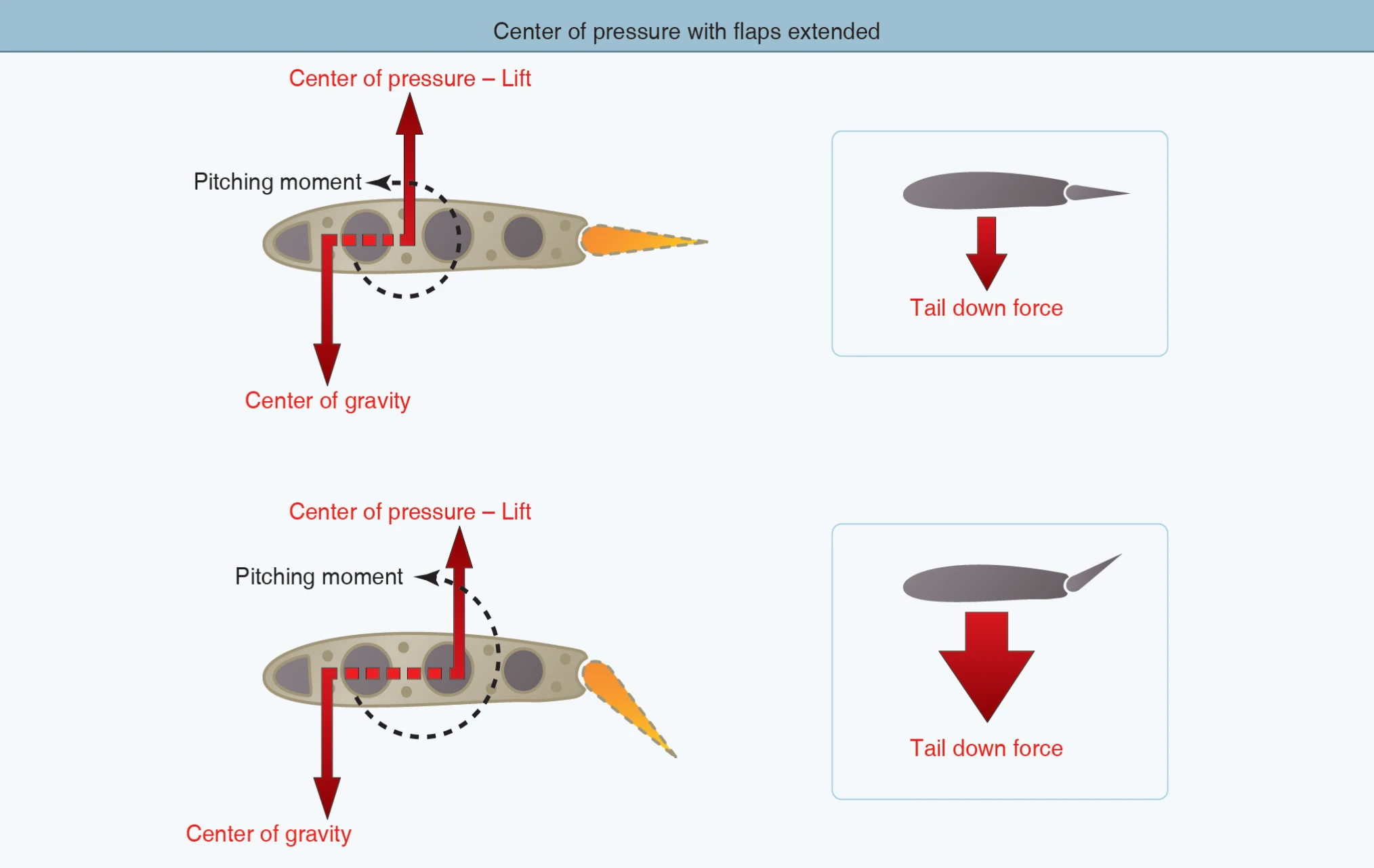
During a go-around, the pilot should carefully monitor pitch and airspeed and expect that the degree of flap deflection and the design configuration of the horizontal tail relative to the wing will affect go-around characteristics. The pilot should carefully monitor pitch and airspeed, control flap retraction to minimize altitude loss, and use rudder for coordination. Considering these factors, it is good practice to extend the same degree of flaps at the same point in the landing pattern for each landing. Consistent use of flaps in the traffic pattern allows for a preplanned and familiar go-around sequence based on the airplane’s position in the landing pattern.
There is no single formula to determine the degree of flap deflection to be used on landing because a landing involves variables that are dependent on each other. The AFM/POH for the particular airplane contains the manufacturer’s recommendations for some landing situations. On the other hand, AFM/POH information on flap usage for takeoff is more precise. The manufacturer’s requirements are based on the climb performance produced by a given flap design. Under no circumstances should a flap setting given in the AFM/POH be exceeded for takeoff.
Controllable-Pitch Propeller
Fixed-pitch propellers are designed for best efficiency at one particular revolutions per minute (rpm) setting and one airspeed. A fixed-pitch propeller provides suitable performance in a narrow range of airspeeds. However, fixed-pitch efficiency suffers considerably when operating outside of this range. To provide improved propeller efficiency through a wide range of operation, the propeller blade angle needs to be controllable.
Constant-Speed Propeller
A constant-speed propeller keeps the blade angle adjusted for maximum efficiency during most flight conditions. The pilot controls the engine rpm indirectly by means of a propeller control, which is connected to the propeller governor. For maximum takeoff power, the propeller control is moved all the way forward to the low pitch/high rpm position, and the throttle is moved forward to the maximum allowable manifold pressure position. [Figure 12- 6] To reduce power for climb or cruise, the pilot reduces manifold pressure to the desired value with the throttle, and then reduces engine rpm by moving the propeller control back toward the high pitch/low rpm position. The pilot sets the rpm accurately using the tachometer.
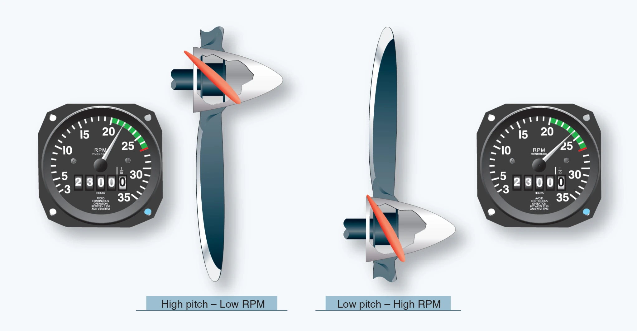
When an airplane engine runs at a constant governed speed, the torque (force) exerted by the engine at the propeller shaft equals the force resisting the moving blades. The pilot uses the propeller control to change engine rpm by adjusting the propeller blade pitch, which increases or decreases the air resistance on the rotating propeller. For example, pulling back on the propeller control moves the propeller blades to a higher pitch. This increases the air resistance exerted on the spinning propeller and puts an additional load on the engine, which causes it to slow down until the forces reach equilibrium. Advancing the propeller control reduces the propeller blade pitch. This reduces the resistance of the air against the propeller. In response, the engine rpm increases until the opposing forces balance. In order for this system to function, a constant-speed propeller governor needs the means to sense engine rpm and a means to control the propeller AOA. In most cases, the governor is geared to the engine crankshaft giving it a means to sense engine rpm. The "Blade Angle Control" section of this chapter discusses the ways a propeller governor adjusts propeller blade angle.
Other factors affect constant-speed propeller blade pitch. When an airplane is nosed up into a climb from level flight, the engine tends to slow down. Since the governor is sensitive to small changes in engine rpm, it decreases the blade angle just enough to keep the engine speed constant. If the airplane is nosed down into a dive, the governor increases the blade angle just enough to keep the engine speed constant. This allows the engine to maintain a constant rpm and power output. The pilot can also set engine power output by changing rpm at a constant manifold pressure; by changing the manifold pressure at a constant rpm; or by changing both rpm and manifold pressure. The constant-speed propeller makes it possible to obtain an infinite number of power settings.
Takeoff, Climb, and Cruise
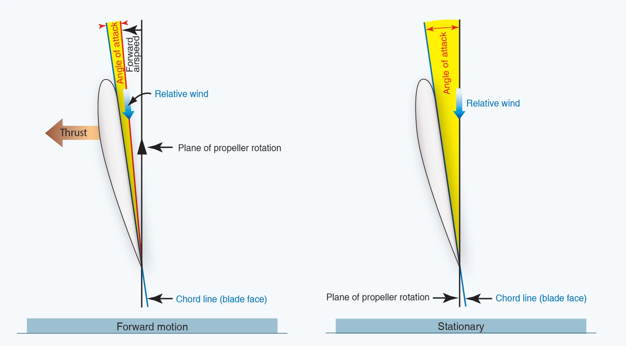
During takeoff, when the forward motion of the airplane is at a low speed and when maximum power and thrust are required, the constant-speed propeller sets up a low propeller blade pitch. The low blade angle keeps the blade angle of attack, with respect to the relative wind, small and efficient at the low speed. [Figure 12-7]
At the same time, low blade pitch allows the propeller to handle a smaller mass of air per revolution. This light propeller load allows the engine to turn at maximum rpm and develop maximum engine power. Although the mass of air per revolution is small, the number of rpm is high, and propeller thrust is maximized until brake release. Thrust is maximum at the beginning of the takeoff roll and then decreases as the airplane gains speed.