
Chapter 12
Transition to Complex Airplanes
Landing Gear Safety Devices
Most airplanes with a retractable landing gear have a gear warning horn that sounds when the airplane is configured for landing and the landing gear is not down and locked. Normally, the horn is linked to the throttle or flap position and/or the airspeed indicator so that when the airplane is below a certain airspeed, configuration, or power setting with the gear retracted, the warning horn sounds.
Accidental retraction of a landing gear may be prevented by such devices as mechanical downlocks, safety switches, and ground locks. Mechanical downlocks are built-in components of a gear retraction system and are operated automatically by the gear retraction system. To prevent accidental operation of the downlocks and inadvertent landing gear retraction while the airplane is on the ground, electrically-operated safety switches are installed.
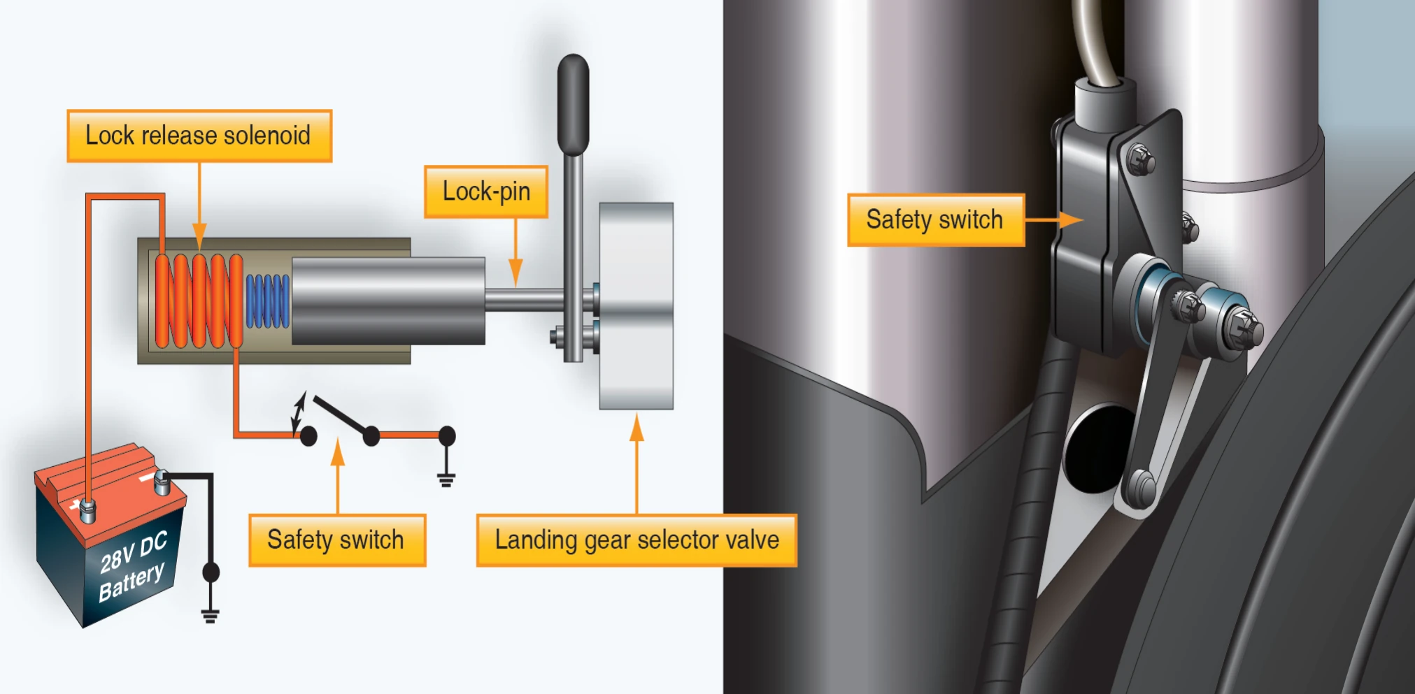
A landing gear safety switch, sometimes referred to as a squat switch, is usually mounted in a bracket on one of the main gear shock struts. [Figure 12-12] When the strut is compressed by the weight of the airplane, the switch opens the electrical circuit to the motor or mechanism that powers retraction. In this way, if the landing gear switch in the flight deck is placed in the RETRACT position when weight is on the gear, the gear remains extended, and the warning horn may sound as an alert to the unsafe condition. Once the weight is off the gear, however, such as on takeoff, the safety switch releases and the gear retracts.
Many airplanes are equipped with removable safety devices to prevent collapse of the gear when the airplane is on the ground. These devices are called ground locks. One common type is a pin installed in aligned holes drilled in two or more units of the landing gear support structure. Another type is a spring-loaded clip designed to fit around and hold two or more units of the support structure together. All types of ground locks usually have red streamers permanently attached to them to readily indicate whether or not they are installed.
Emergency Gear Extension Systems
The emergency gear extension system lowers the landing gear if the main power system fails. Some airplanes have an emergency release handle in the flight deck, which is connected through a mechanical linkage to the gear uplocks. When the handle is operated, it releases the uplocks and allows the gear to free fall or extend under their own weight. [Figure 12-13]
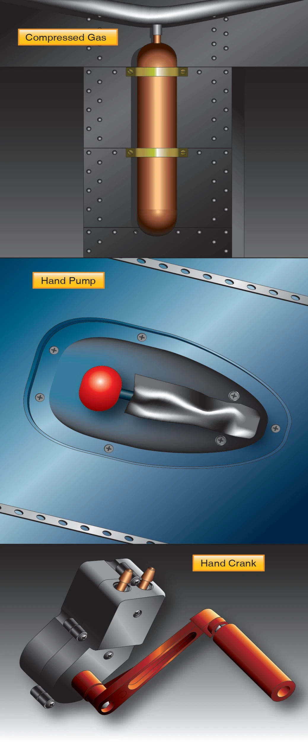
On other airplanes, release of the uplock is accomplished using compressed gas, which is directed to uplock release cylinders. In some airplanes, design configurations make emergency extension of the landing gear by gravity and air loads alone impossible or impractical. In these airplanes, provisions are included for forceful gear extension in an emergency. Some installations are designed so that either hydraulic fluid or compressed gas provides the necessary pressure, while others use a manual system, such as a hand crank for emergency gear extension. [Figure 12-14] Hydraulic pressure for emergency operation of the landing gear may be provided by an auxiliary hand pump, an accumulator, or an electrically-powered hydraulic pump depending on the design of the airplane.
Operational Procedures
Preflight
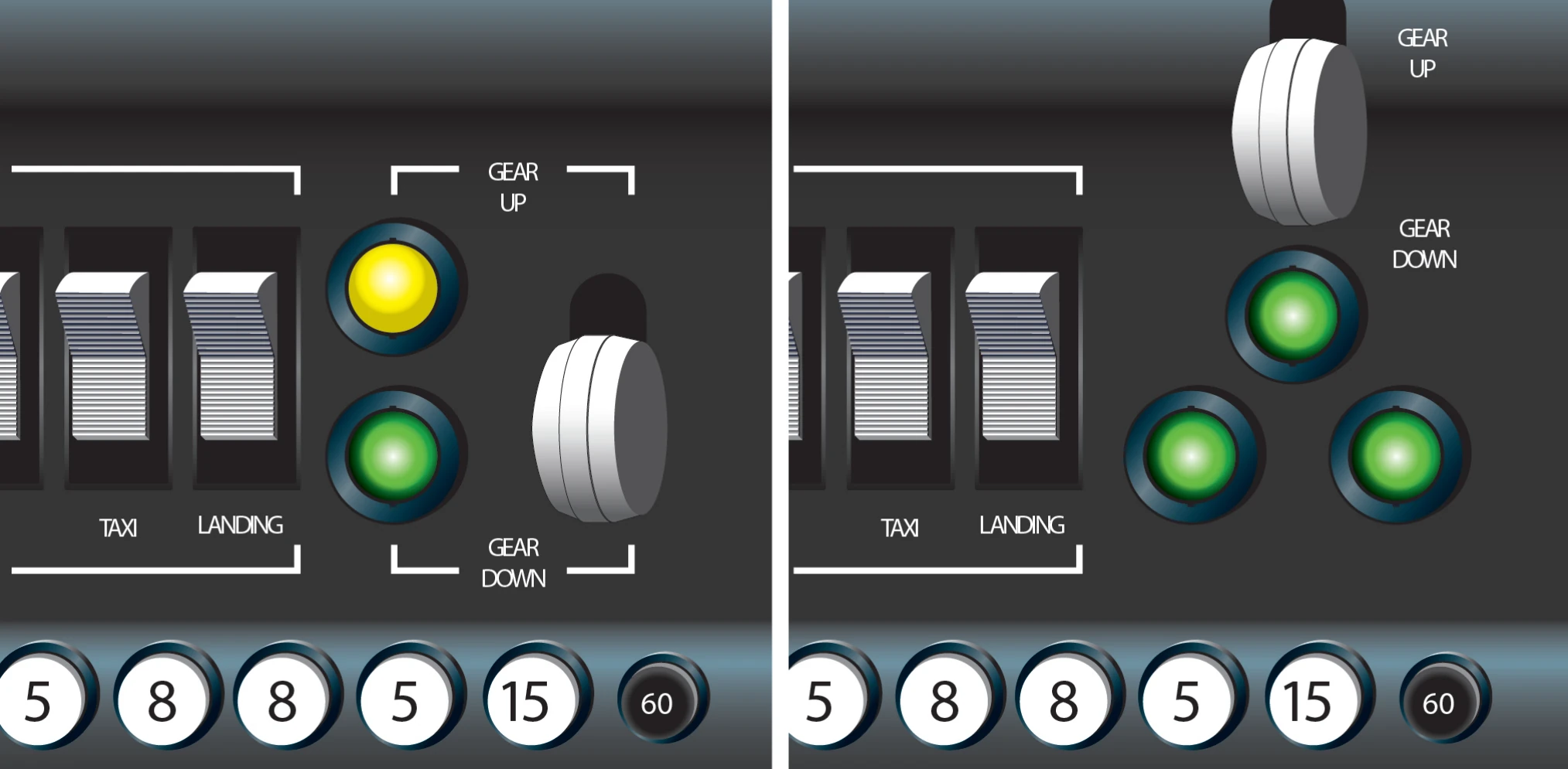
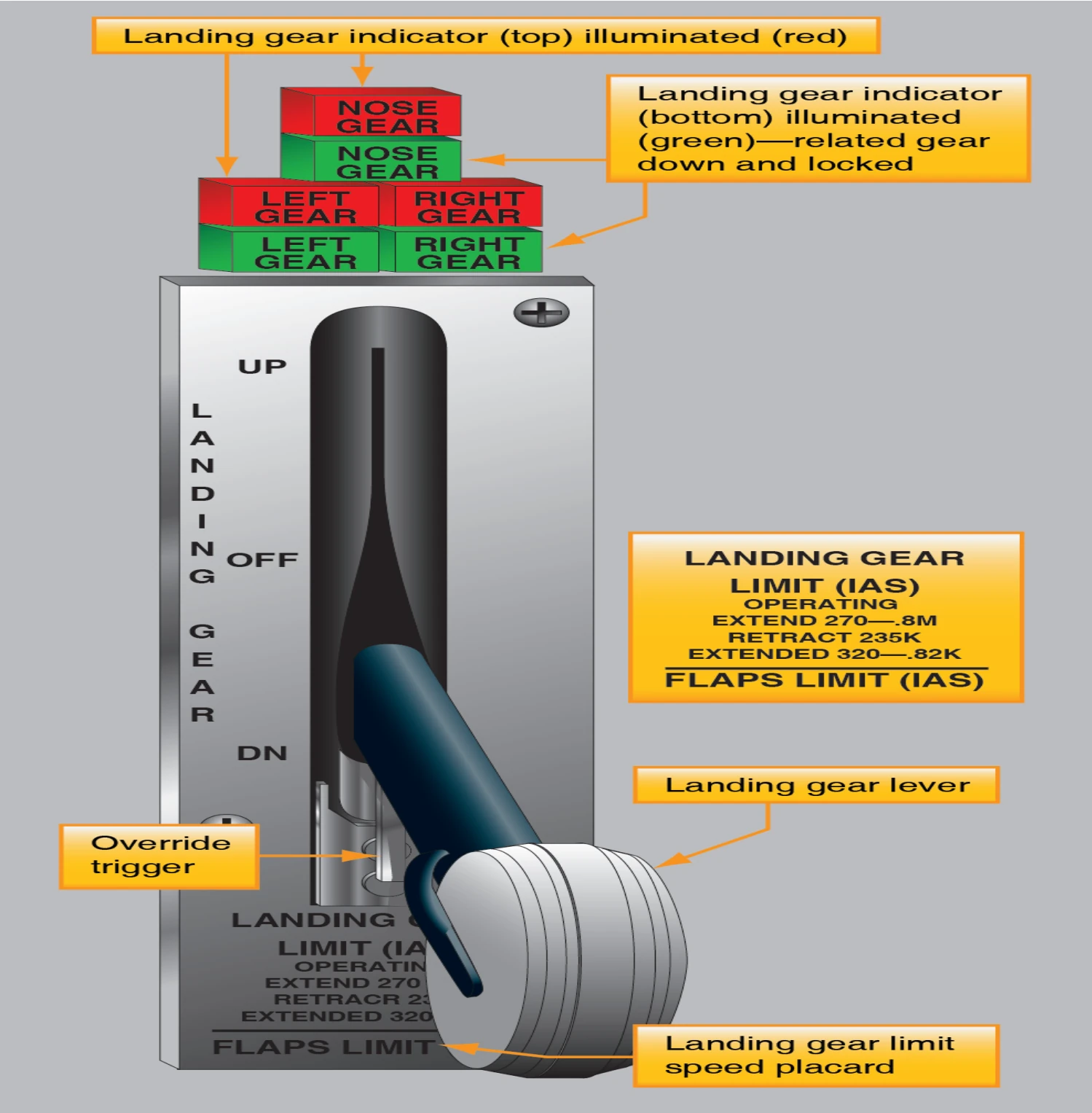
Because of their complexity, retractable landing gear demands a close inspection prior to every flight. The inspection should begin inside the flight deck. First, make certain that the landing gear selector switch is in the GEAR DOWN position. Then, turn on the battery master switch and ensure that the landing gear position indicators show that the gear is down and locked.
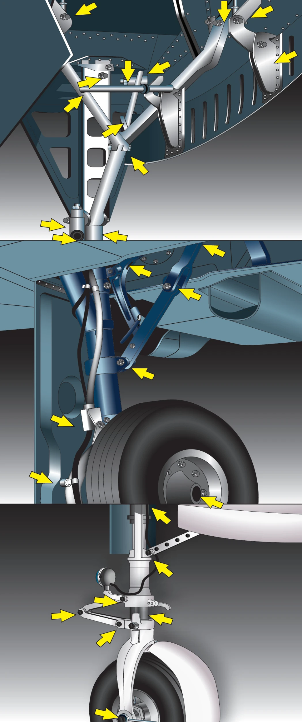
External inspection of the landing gear consists of checking individual system components. [Figure 12-14] The landing gear, wheel well, and adjacent areas should be clean and free of mud and debris. Dirty switches and valves may cause false safe light indications or interrupt the extension cycle before the landing gear is completely down and locked. The wheel wells should be clear of any obstructions, as foreign objects may damage the gear or interfere with its operation. Bent gear doors may be an indication of possible problems with normal gear operation.
Ensure shock struts are properly inflated and that the pistons are clean. Check main gear and nose gear uplock and downlock mechanisms for general condition. Power sources and retracting mechanisms are checked for general condition, obvious defects, and security of attachment. Check hydraulic lines for signs of chafing and leakage at attach points. Warning system micro switches (squat switches) are checked for cleanliness and security of attachment. Actuating cylinders, sprockets, universal joints, drive gears, linkages, and any other accessible components are checked for condition and obvious defects. The airplane structure to which the landing gear is attached is checked for distortion, cracks, and general condition. All bolts and rivets should be intact and secure.
Takeoff and Climb
Normally, the landing gear is retracted after lift-off when the airplane has reached an altitude where, in the event of an engine failure or other emergency requiring an aborted takeoff, the airplane could no longer be landed on the runway. This procedure, however, may not apply to all situations. Preplan landing gear retraction taking into account the following: