
Chapter 15
Transition to Turbopropeller-Powered Airplanes
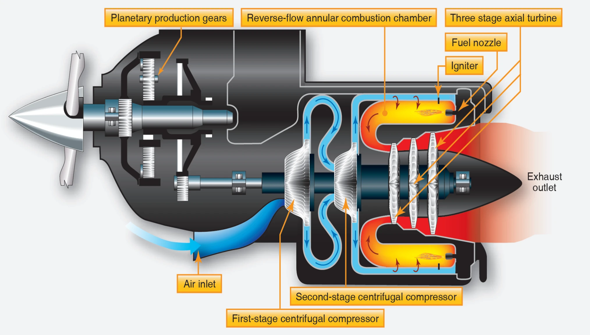
The gas mixture is initially ignited by high-energy igniter plugs, and the expanding combustion gases flow to the turbine. The energy of the hot, high-velocity gases is converted to torque on the main shaft by the turbine rotors. The reduction gear converts the high rpm—low torque of the main shaft to low rpm—high torque to drive the accessories and the propeller. The spent gases leaving the turbine are directed to the atmosphere by the exhaust pipe.
Most of the air passing through the engine provides internal cooling. Only about 10 percent of the air that passes through the engine is actually used in the combustion process. Up to approximately 20 percent of the compressed air may be bled off for the purpose of heating, cooling, cabin pressurization, and pneumatic systems. Over half the engine power is devoted to driving the compressor, and it is the compressor that can potentially produce very high drag in the case of a failed, windmilling engine.
In the fixed-shaft constant-speed engine, the engine rpm may be varied within a narrow range of 96 percent to 100 percent. During ground operation, the rpm may be reduced to 70 percent. In flight, the engine operates at a constant speed that is maintained by the governing section of the propeller. Power changes are made by increasing fuel flow and propeller blade angle rather than engine speed. An increase in fuel flow causes an increase in temperature and a corresponding increase in energy available to the turbine. The turbine absorbs more energy and transmits it to the propeller in the form of torque. The increased torque forces the propeller blade angle to be increased to maintain the constant speed. Turbine temperature is a very important factor to be considered in power production. It is directly related to fuel flow and thus to the power produced. It needs to be limited because of strength and durability of the material in the combustion and turbine section. The control system schedules fuel flow to produce specific temperatures and to limit those temperatures so that the temperature tolerances of the combustion and turbine sections are not exceeded. The engine is designed to operate for its entire life at 100 percent. All of its components, such as compressors and turbines, are most efficient when operated at or near the rpm design point.
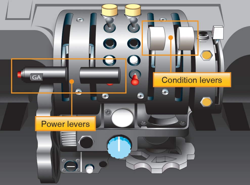
Powerplant (engine and propeller) control is achieved by means of a power lever and a condition lever for each engine. [Figure 15-3] There is no mixture control and/or rpm lever as found on piston-engine airplanes.
On the fixed-shaft constant-speed turboprop engine, the power lever is advanced or retarded to increase or decrease forward thrust. The power lever is also used to provide reverse thrust. The condition lever sets the desired engine rpm within a narrow range between that appropriate for ground operations and flight.
Powerplant instrumentation in a fixed-shaft turboprop engine typically consists of the following basic indicators. [Figure 15-4]
- Torque or horsepower
- Interturbine temperature (ITT)
- Fuel flow
- RPM
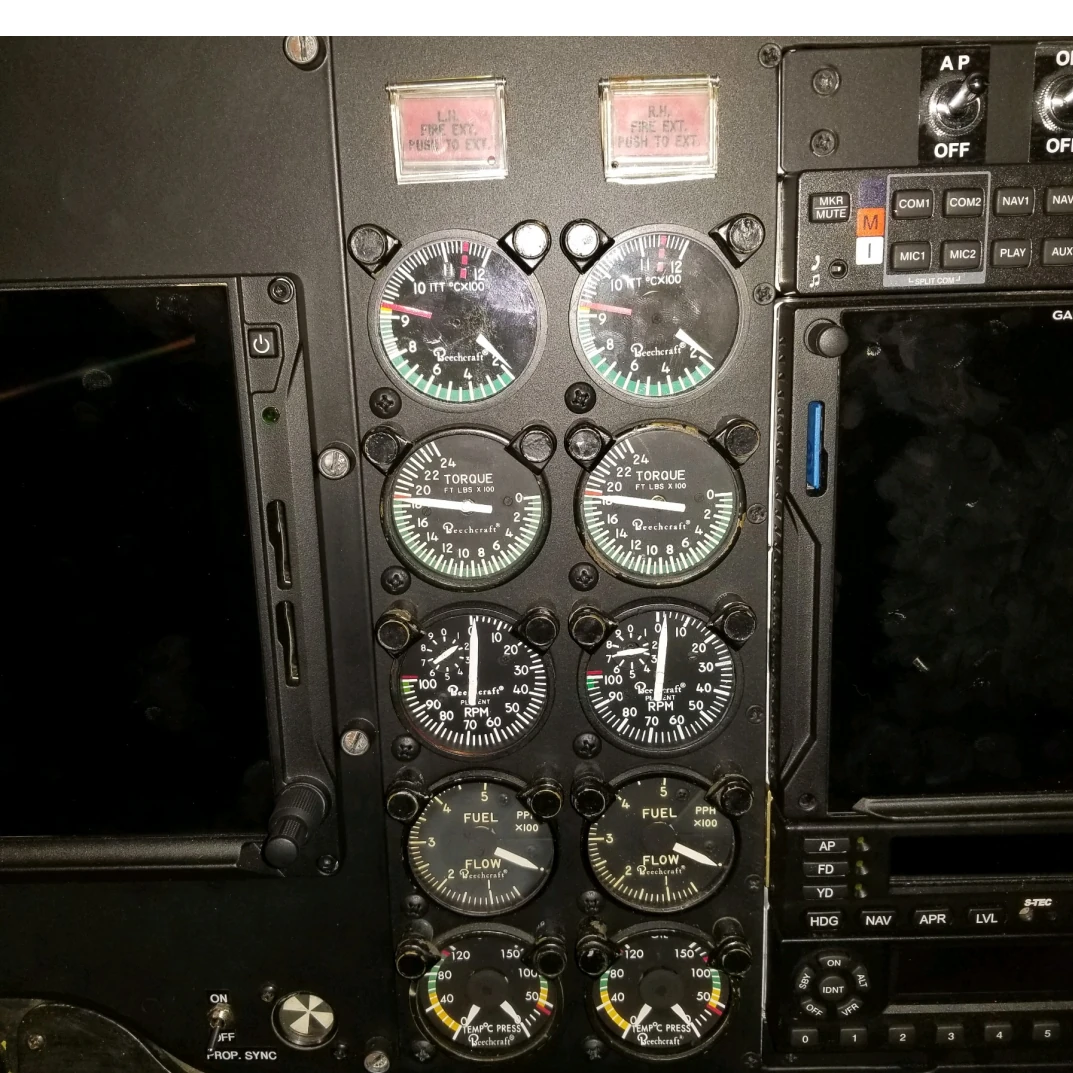
Torque developed by the turbine section is measured by a torque sensor. The torque is then reflected on the instrument panel horsepower gauge calibrated in horsepower times 100. ITT is a measurement of the combustion gas temperature between the first and second stages of the turbine section. The gauge is calibrated in degrees Celsius (°C). Propeller rpm is reflected on a tachometer as a percentage of maximum rpm. Normally, a vernier indicator on the gauge dial indicates rpm in 1 percent graduations as well. The fuel flow indicator indicates fuel flow rate in pounds per hour.
Propeller feathering in a fixed-shaft constant-speed turboprop engine is normally accomplished with the condition lever. An engine failure in this type engine, however, results in a serious drag condition due to the large power requirements of the compressor being absorbed by the propeller. This could create a serious airplane control problem in twin-engine airplanes unless the failure is recognized immediately and the affected propeller feathered. For this reason, the fixed-shaft turboprop engine is equipped with negative torque sensing (NTS).
NTS is a condition wherein propeller torque drives the engine, and the propeller is automatically driven to high pitch to reduce drag. The function of the negative torque sensing system is to limit the torque the engine can extract from the propeller during windmilling and thereby prevent large drag forces on the airplane. The NTS system causes a movement of the propeller blades automatically toward their feathered position should the engine suddenly lose power while in flight. The NTS system is an emergency backup system in the event of sudden engine failure. It is not a substitution for the feathering device controlled by the condition lever.
Split-Shaft/Free Turbine Engine
In a free power-turbine engine, such as the Pratt & Whitney PT-6 engine, the propeller is driven by a separate turbine through reduction gearing. The propeller is not on the same shaft as the basic engine turbine and compressor. [Figure 15-5] Unlike the fixed-shaft engine, in the split-shaft engine the propeller can be feathered in flight or on the ground with the basic engine still running. The free power-turbine design allows the pilot to select a desired propeller governing rpm, regardless of basic engine rpm.
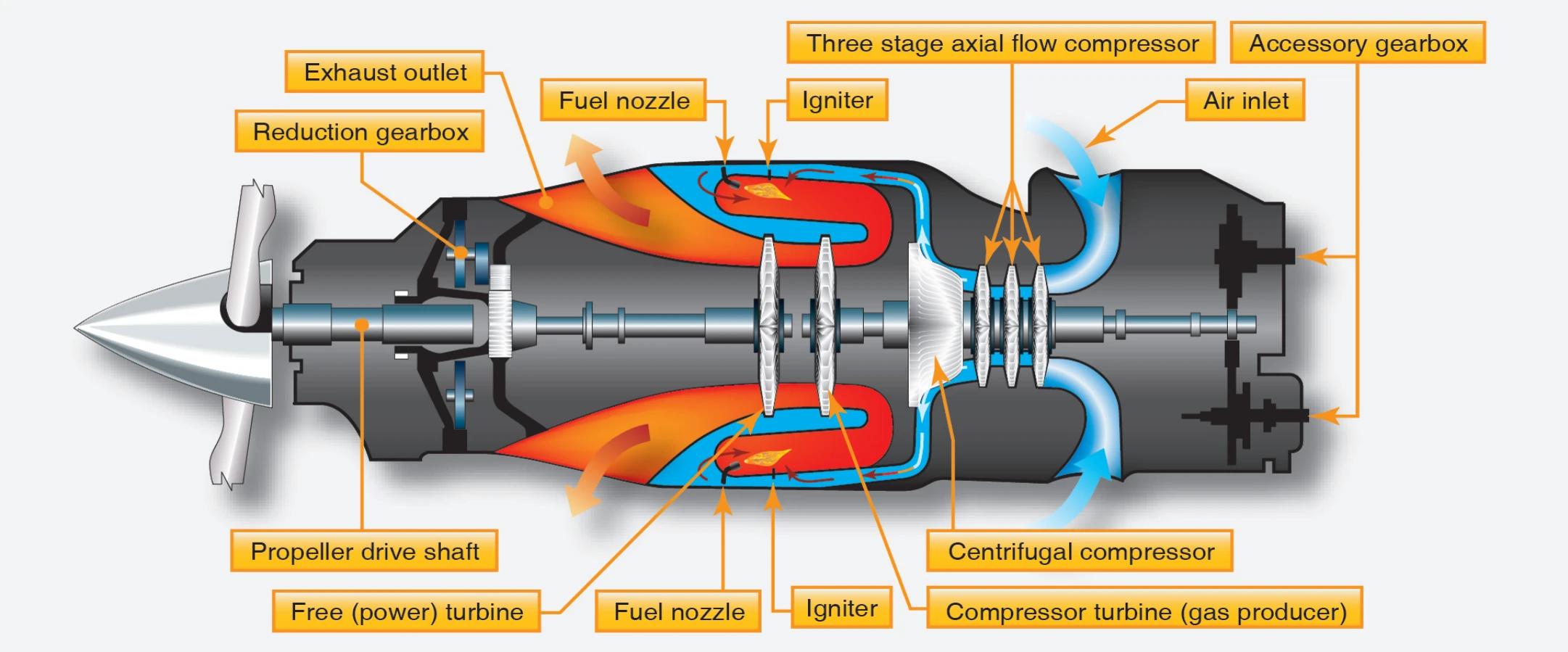
A typical free power-turbine engine has two independent counter-rotating turbines. One turbine drives the compressor, while the other drives the propeller through a reduction gearbox. The compressor in the basic engine consists of three axial flow compressor stages combined with a single centrifugal compressor stage. The axial and centrifugal stages are assembled on the same shaft and operate as a single unit.
Inlet air enters the engine via a circular plenum near the rear of the engine and flows forward through the successive compressor stages. The flow is directed outward by the centrifugal compressor stage through radial diffusers before entering the combustion chamber, where the flow direction is actually reversed. The gases produced by combustion are once again reversed to expand forward through each turbine stage. After leaving the turbines, the gases are collected in a peripheral exhaust scroll and are discharged to the atmosphere through two exhaust ports near the front of the engine.
A pneumatic fuel control system schedules fuel flow to maintain the power set by the gas generator power lever. Except in the beta range, propeller speed within the governing range remains constant at any selected propeller control lever position through the action of a propeller governor.
The accessory drive at the aft end of the engine provides power to drive fuel pumps, fuel control, oil pumps, a starter/generator, and a tachometer transmitter. At this point, the speed of the drive (N1 ) is the true speed of the compressor side of the engine, approximately 37,500 rpm.