
Chapter 15
Transition to Turbopropeller-Powered Airplanes
Powerplant (engine and propeller) operation is achieved by three sets of controls for each engine: the power lever, propeller lever, and condition lever. [Figure 15-6] The power lever serves to control engine power in the range from idle through takeoff power. Forward or aft motion of the power lever increases or decreases gas generator rpm (N1 ) and thereby increases or decreases engine power. The propeller lever is operated conventionally and controls the constant-speed propellers through the primary governor. The propeller rpm range is normally from 1,500 to 1,900. The condition lever controls the flow of fuel to the engine. Like the mixture lever in a piston-powered airplane, the condition lever is located at the far right of the power quadrant. But the condition lever on a turboprop engine is really just an on/off valve for delivering fuel. There are HIGH IDLE and LOW IDLE positions for ground operations, but condition levers have no metering function. Leaning is not required in turbine engines; this function is performed automatically by a dedicated fuel control unit.
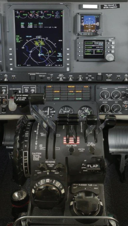
Engine instruments in a split-shaft/free turbine engine typically consist of the following basic indicators. [Figure 15-7]
- ITT indicator
- Torquemeter
- Propeller tachometer
- N1 (gas generator) tachometer
- Fuel flow indicator
- Oil temperature/pressure indicator
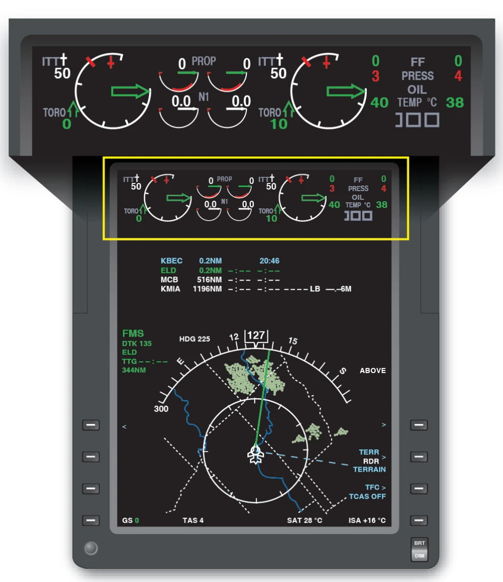
The ITT indicator gives an instantaneous reading of engine gas temperature between the compressor turbine and the power turbines. The torquemeter responds to power lever movement and gives an indication in foot-pounds (ft/lb) of the torque being applied to the propeller. Because in the free turbine engine the propeller is not attached physically to the shaft of the gas turbine engine, two tachometers are justified—one for the propeller and one for the gas generator. The propeller tachometer is read directly in revolutions per minute. The N1 or gas generator is read in percent of rpm. In the Pratt & Whitney PT-6 engine, it is based on a figure of 37,000 rpm at 100 percent. Maximum continuous gas generator is limited to 38,100 rpm or 101.5 percent N1.
The ITT indicator and torquemeter are used to set takeoff power. Climb and cruise power are established with the torquemeter and propeller tachometer while observing ITT limits. Gas generator (N1 ) operation is monitored by the gas generator tachometer. Proper observation and interpretation of these instruments provide an indication of engine performance and condition.
Reverse Thrust and Beta Range Operations
The thrust that a propeller provides is a function of the angle of attack (AOA) at which the air strikes the blades, and the speed at which this occurs. The AOA varies with the pitch angle of the propeller.
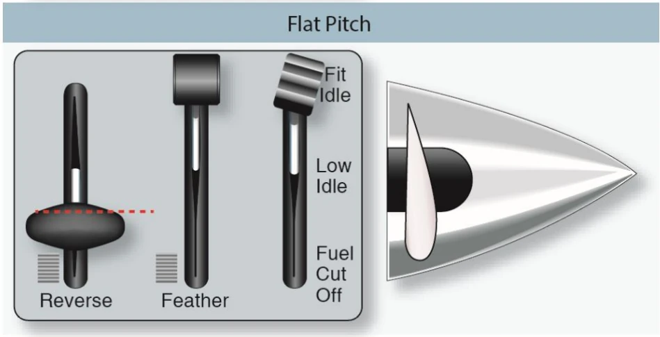
Forward pitch produces forward thrust—higher pitch angles being required at higher airplane speeds. [Figure 15-8A] So called “flat pitch,” shown in Figure 15-8B, is the blade position offering minimum resistance to rotation and no net thrust for moving the airplane.

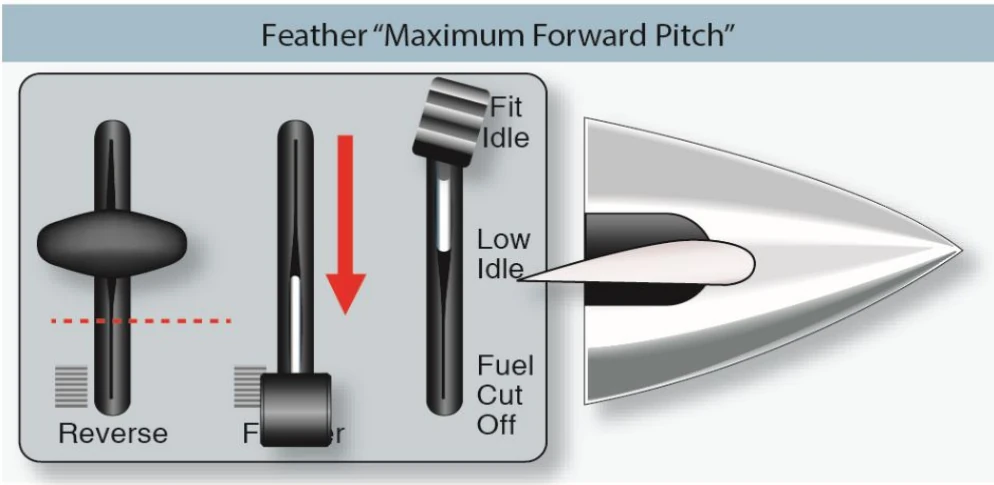
The “feathered” position is the highest pitch angle obtainable. [Figure 15-8C] The feathered position produces no forward thrust. The propeller is generally placed in feather only in case of in-flight engine failure to minimize drag and prevent the air from using the propeller as a turbine.
In the “reverse” pitch position, the engine/propeller turns in the same direction as in the normal (forward) pitch position, but the propeller blade angle is positioned to the other side of flat pitch. [Figure 15-8D] In reverse pitch, air is pushed away from the airplane rather than being drawn over it. Reverse pitch results in braking action, rather than forward thrust of the airplane. It is used for backing away from obstacles when taxiing, controlling taxi speed, or to aid in bringing the airplane to a stop during the landing roll. Reverse pitch does not mean reverse rotation of the engine. The engine delivers power just the same, no matter which side of flat pitch the propeller blades are positioned.
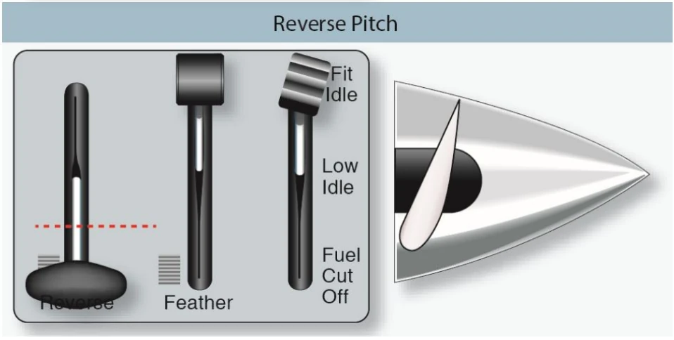
With a turboprop engine, in order to obtain enough power for flight, the power lever is placed somewhere between flight idle (in some engines referred to as “high idle”) and maximum. The power lever directs signals to a fuel control unit to manually select fuel. The propeller governor selects the propeller pitch needed to keep the propeller/engine on speed. This is referred to as the propeller governing or “alpha” mode of operation. When positioned aft of flight idle, however, the power lever directly controls propeller blade angle. This is known as the “beta” range of operation.
The beta range of operation consists of power lever positions from flight idle to maximum reverse. Beginning at power lever positions just aft of flight idle, propeller blade pitch angles become progressively flatter with aft movement of the power lever until they go beyond maximum flat pitch and into negative pitch, resulting in reverse thrust. While in a fixed-shaft/constant-speed engine, the engine speed remains largely unchanged as the propeller blade angles achieve their negative values. On the split-shaft PT-6 engine, as the negative 5° position is reached, further aft movement of the power lever also results in a progressive increase in engine (N1 ) rpm until a maximum value of about negative 11° of blade angle and 85 percent N1 are achieved.
Operating in the beta range and/or with reverse thrust requires specific techniques and procedures depending on the particular airplane make and model. Specific engine parameters and limitations for operations within this area should be adhered to. It is essential that a pilot transitioning to turboprop airplanes becomes knowledgeable and proficient in these areas, which are unique to turbine-engine powered airplanes.