Chapter 1
Aircraft Structures
beam of the wing and parallel to, and outboard from, the inboard edge of the flap.
- Nacelle station (NC or Nac. Sta.) is measured either forward of or behind the front spar of the wing and perpendicular to a designated water line.
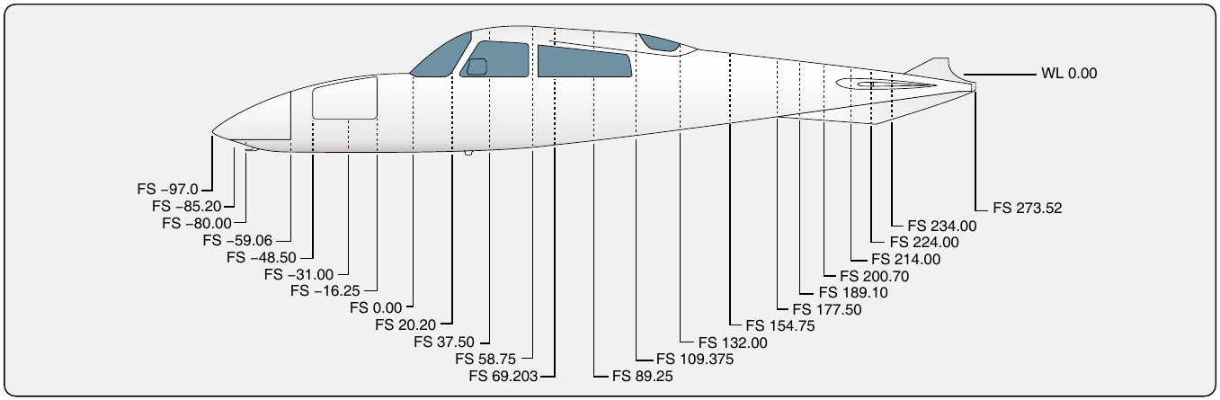
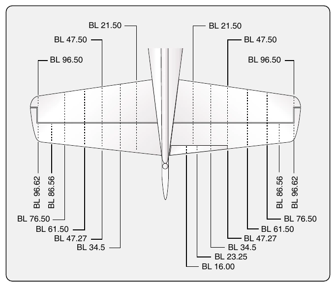
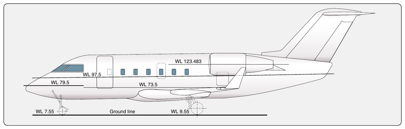
In addition to the location stations listed above, other measurements are used, especially on large aircraft. Thus, there may be horizontal stabilizer stations (HSS), vertical stabilizer stations (VSS) or powerplant stations (PPS). [Figure 1-91] In every case, the manufacturer’s terminology and station location system should be consulted before locating a point on a particular aircraft.
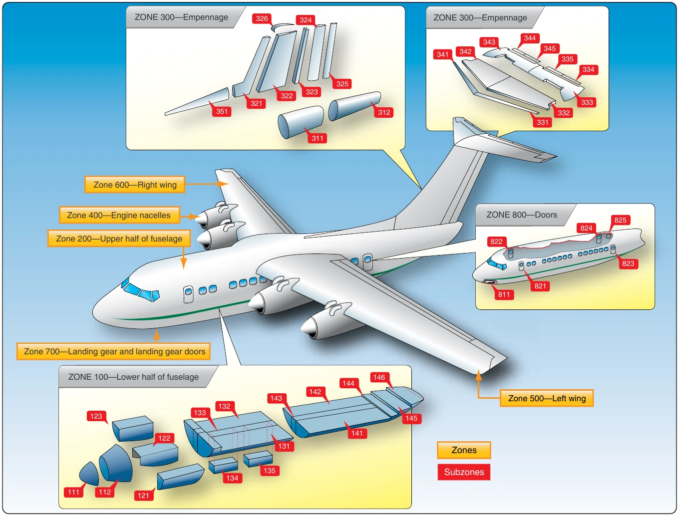
Another method is used to facilitate the location of aircraft components on air transport aircraft. This involves dividing the aircraft into zones. These large areas or major zones are further divided into sequentially numbered zones and subzones. The digits of the zone number are reserved and indexed to indicate the location and type of system of which the component is a part. Figure 1-92 illustrates these zones and subzones on a transport category aircraft.
Access & Inspection Panels
Quick access to the accessories and other equipment carried in the fuselage is provided for by numerous access doors, inspection plates, landing wheel wells, and other openings.
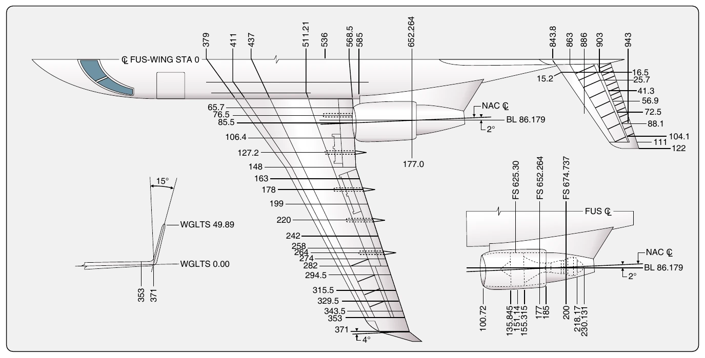
Servicing diagrams showing the arrangement of equipment and location of access doors are supplied by the manufacturer in the aircraft maintenance manual.
Knowing where a particular structure or component is located on an aircraft needs to be combined with gaining access to that area to perform the required inspections or maintenance. To facilitate this, access and inspection panels are located on most surfaces of the aircraft. Small panels that are hinged or removable allow inspection and servicing. Large panels and doors allow components to be removed and installed, as well as human entry for maintenance purposes.
The underside of a wing, for example, sometimes contains dozens of small panels through which control cable components can be monitored and fittings greased. Various drains and jack points may also be on the underside of the wing. The upper surface of the wings typically have fewer access panels because a smooth surface promotes better laminar airflow, which causes lift. On large aircraft, walkways are sometimes designated on the wing upper surface to permit safe navigation by mechanics and inspectors to critical structures and components located along the wing’s leading and trailing edges. Wheel wells and special component bays are places where numerous components and accessories are grouped together for easy maintenance access.
Panels and doors on aircraft are numbered for positive identification. On large aircraft, panels are usually numbered sequentially containing zone and subzone information in the panel number. Designation for a left or right side location on the aircraft is often indicated in the panel number. This could be with an “L” or “R,” or panels on one side of the aircraft could be odd numbered and the other side even numbered. The manufacturer’s maintenance manual explains the panel numbering system and often has numerous diagrams and tables showing the location of various components and under which panel they may be found. Each manufacturer is entitled to develop its own panel numbering system.
Helicopter Structures
The structures of the helicopter are designed to give the helicopter its unique flight characteristics. A simplified explanation of how a helicopter flies is that the rotors are rotating airfoils that provide lift similar to the way wings provide lift on a fixed-wing aircraft. Air flows faster over the curved upper surface of the rotors, causing a negative pressure and thus, lifting the aircraft. Changing the angle of attack of the rotating blades increases or decreases lift, respectively raising or lowering the helicopter. Tilting the rotor plane of rotation causes the aircraft to move horizontally. Figure 1-93 shows the major components of a typical helicopter.
Airframe
The airframe, or fundamental structure, of a helicopter can be made of either metal or wood composite materials, or some combination of the two. Typically, a composite component consists of many layers of fiber-impregnated resins, bonded to form a smooth panel. Tubular and sheet metal substructures are usually made of aluminum, though stainless steel or titanium are sometimes used in areas subject to higher stress or heat. Airframe design encompasses engineering, aerodynamics, materials technology, and manufacturing methods to achieve favorable balances of performance, reliability, and cost.