
Chapter 1
Aircraft Structures
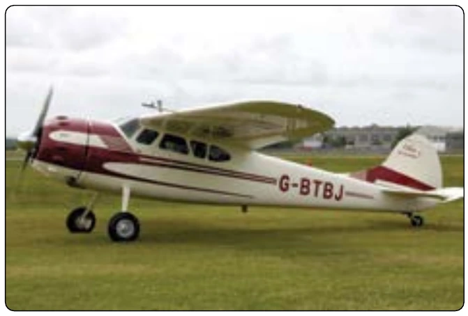
Conventional gear is useful and is still found on certain models of aircraft manufactured today, particularly aerobatic aircraft, crop dusters, and aircraft designed for unpaved runway use. It is typically lighter than tricycle gear which requires a stout, fully shock absorbing nose wheel assembly. The tail wheel configuration excels when operating out of unpaved runways. With the two strong main gear forward providing stability and directional control during takeoff roll, the lightweight tail wheel does little more than keep the aft end of the fuselage from striking the ground. As mentioned, at a certain speed, the air flowing over the elevator is sufficient for it to raise the tail off the ground. As speed increases further, the two main wheels under the center of gravity are very stable.
Tricycle Gear Configuration
Tricycle gear is the most prevalent landing gear configuration in aviation. In addition to the main wheels, a shock absorbing nose wheel is at the forward end of the fuselage. Thus, the center of gravity is then forward of the main wheels. The tail of the aircraft is suspended off the ground and clear view straight ahead from the flight deck is given. Ground looping is nearly eliminated since the center of gravity follows the directional nose wheel and remains between the mains.
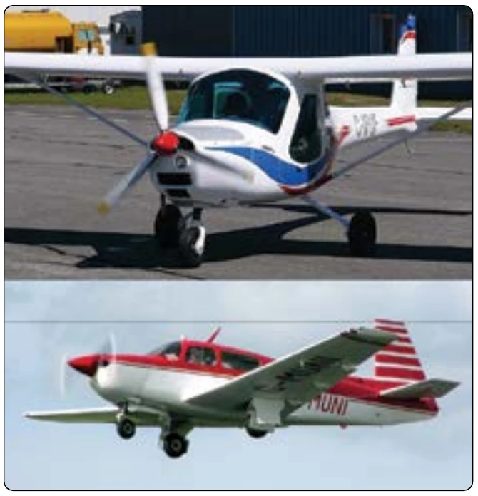
Light aircraft use tricycle gear, as well as heavy aircraft. Twin nose wheels on the single forward strut and massive multistrut/multiwheel main gear may be found supporting the world’s largest aircraft, but the basic configuration is still tricycle. The nose wheel may be steered with the rudder pedals on small aircraft. Larger aircraft often have a nose wheel steering wheel located off to the side of the flight deck. Figure 1-87 shows aircraft with tricycle gear. Chapter 13, Aircraft Landing Gear Systems, discusses landing gear in detail.
Maintaining the Aircraft
Maintenance of an aircraft is of the utmost importance for safe flight. Certificated technicians are committed to perform timely maintenance functions in accordance with the manufacturer’s instructions and under Title 14 of the Code of Federal Regulations (14 CFR). At no time is an act of aircraft maintenance taken lightly or improvised. The consequences of such action could be fatal, and the technician could lose their certificate and face criminal charges.
Airframe, engine, and aircraft component manufacturers are responsible for documenting the maintenance procedures that guide managers and technicians on when and how to perform maintenance on their products. A small aircraft may only require a few manuals, including the aircraft maintenance manual. This volume usually contains the most frequently used information required to maintain the aircraft properly. The Type Certificate Data Sheet (TCDS) for an aircraft also contains critical information. Complex and large aircraft require several manuals to convey correct maintenance procedures adequately. In addition to the maintenance manual, manufacturers may produce such volumes as structural repair manuals, overhaul manuals, wiring diagram manuals, component manuals, and more.
the past, not using the proper tooling has caused damage to critical components, which subsequently failed and led to aircraft crashes and the loss of human life. The technician is responsible for using the correct information, procedures, and tools needed to perform appropriate maintenance or repairs.
Standard aircraft maintenance procedures do exist and can be used by the technician when performing maintenance or a repair. These are found in the FederalAviation Administration (FAA) approved advisory circulars (AC) 43.13-2, Acceptable
Methods, Techniques, and Practices - Aircraft Alterations
and AC 43.13-1, Acceptable Methods, Techniques, and Practices - Aircraft Inspection and Repair. If not addressed by the manufacturer’s literature, the technician may use the procedures outlined in these manuals to complete the work in an acceptable manner. These procedures are not specific to any aircraft or component and typically cover methods used during maintenance of all aircraft. Note that the manufacturer’s instructions supersede the general procedures found in AC 43.13-2 and AC 43.13-1.
All maintenance related actions on an aircraft or component are required to be documented by the performing technician in the aircraft or component logbook. Light aircraft may have only one logbook for all work performed. Some aircraft may have a separate engine logbook for any work performed on the engine(s). Other aircraft have separate propeller logbooks. Large aircraft require volumes of maintenance documentation comprised of thousands of procedures performed by hundreds of technicians. Electronic dispatch and recordkeeping of maintenance performed on large aircraft such as airliners is common. The importance of correct maintenance recordkeeping should not be overlooked.
Location Numbering Systems
Even on small, light aircraft, a method of precisely locating each structural component is required. Various numbering systems are used to facilitate the location of specific wing frames, fuselage bulkheads, or any other structural members on an aircraft. Most manufacturers use some system of station marking. For example, the nose of the aircraft may be designated “zero station,” and all other stations are located at measured distances in inches behind the zero station. Thus, when a blueprint reads “fuselage frame station 137,” that particular frame station can be located 137 inches behind the nose of the aircraft.
To locate structures to the right or left of the center line of an aircraft, a similar method is employed. Many manufacturers consider the center line of the aircraft to be a zero station from which measurements can be taken to the right or left to locate an airframe member. This is often used on the horizontal stabilizer and wings.
The applicable manufacturer’s numbering system and abbreviated designations or symbols should always be reviewed before attempting to locate a structural member. They are not always the same. The following list includes location designations typical of those used by many manufacturers.
- Fuselage stations (Fus. Sta. or FS) are numbered in inches from a reference or zero point known as the reference datum. [Figure 1-88] The reference datum is an imaginary vertical plane at or near the nose of the aircraft from which all fore and aft distances are measured. The distance to a given point is measured in inches parallel to a center line extending through the aircraft from the nose through the center of the tail cone. Some manufacturers may call the fuselage station a body station, abbreviated BS.
- Buttock line or butt line (BL) is a vertical reference plane down the center of the aircraft from which measurements left or right can be made. [Figure 1-89]
- Water line (WL) is the measurement of height in inches perpendicular from a horizontal plane usually located at the ground, cabin floor, or some other easily referenced location. [Figure 1-90]
- Aileron station (AS) is measured outboard from, and parallel to, the inboard edge of the aileron, perpendicular to the rear beam of the wing.
- Flap station (KS) is measured perpendicular to the rear