Chapter 1
Aircraft Structures
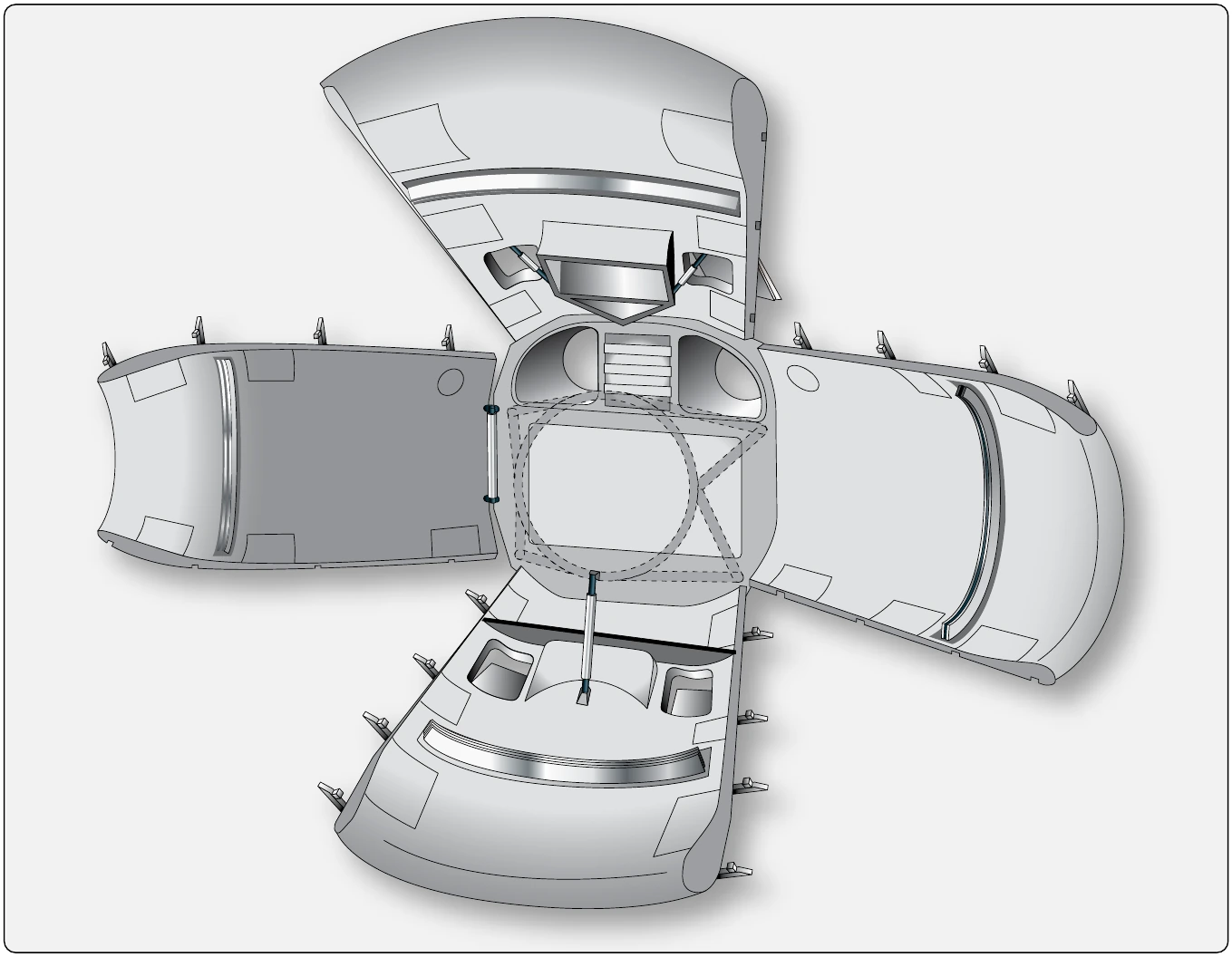
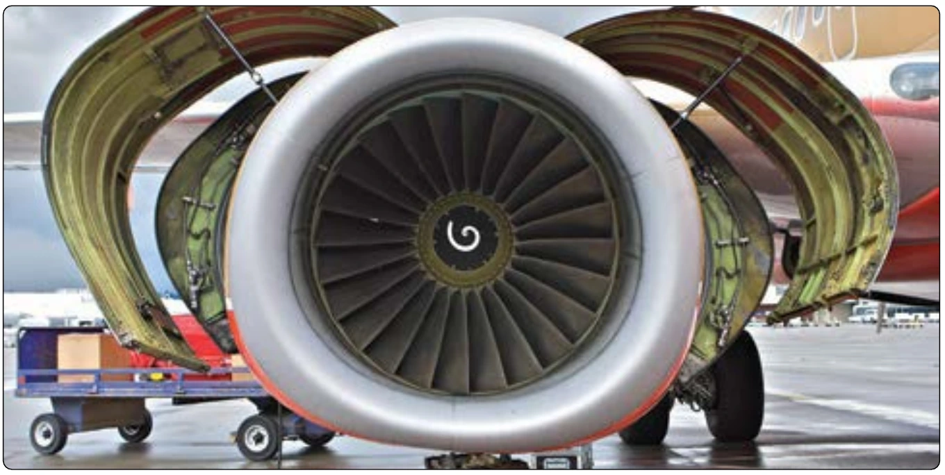
and easily removable panels which can be opened and closed during maintenance. A nose cowl is also a feature on a jet engine nacelle. It guides air into the engine.
Empennage
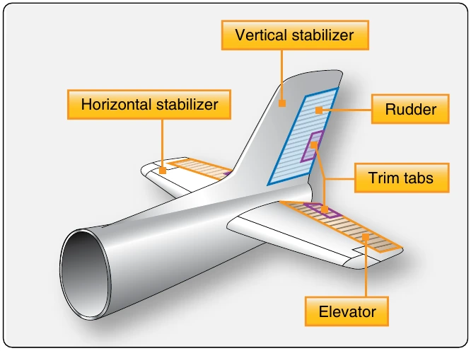
The empennage of an aircraft is also known as the tail section. Most empennage designs consist of a tail cone, fixed aerodynamic surfaces or stabilizers, and movable aerodynamic surfaces.
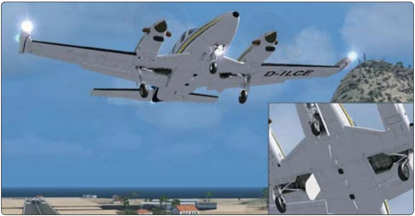
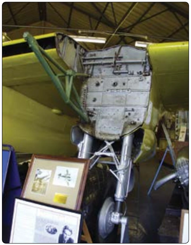
The tail cone serves to close and streamline the aft end of most fuselages. The cone is made up of structural members like those of the fuselage; however, cones are usually of lighter construction since they receive less stress than the fuselage. [Figure 1-46]
The other components of the typical empennage are of heavier construction than the tail cone. These members include fixed surfaces that help stabilize the aircraft and movable surfaces that help to direct an aircraft during flight. The fixed surfaces are the horizontal stabilizer and vertical stabilizer. The movable surfaces are usually a rudder located at the aft edge of the vertical stabilizer and an elevator located at the aft edge the horizontal stabilizer. [Figure 1-47]
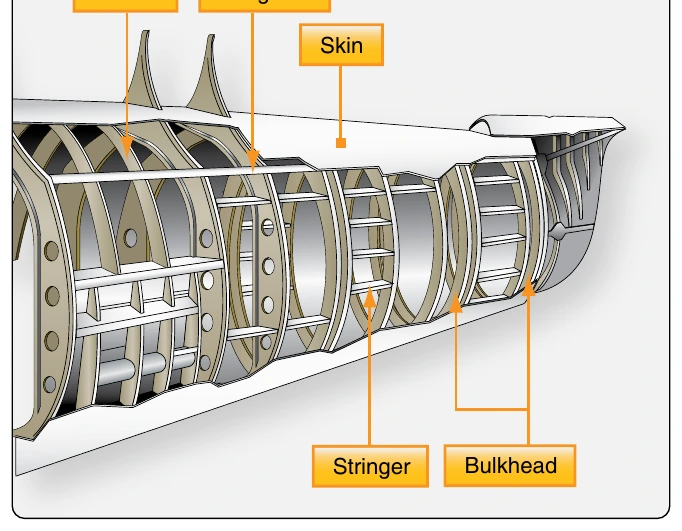
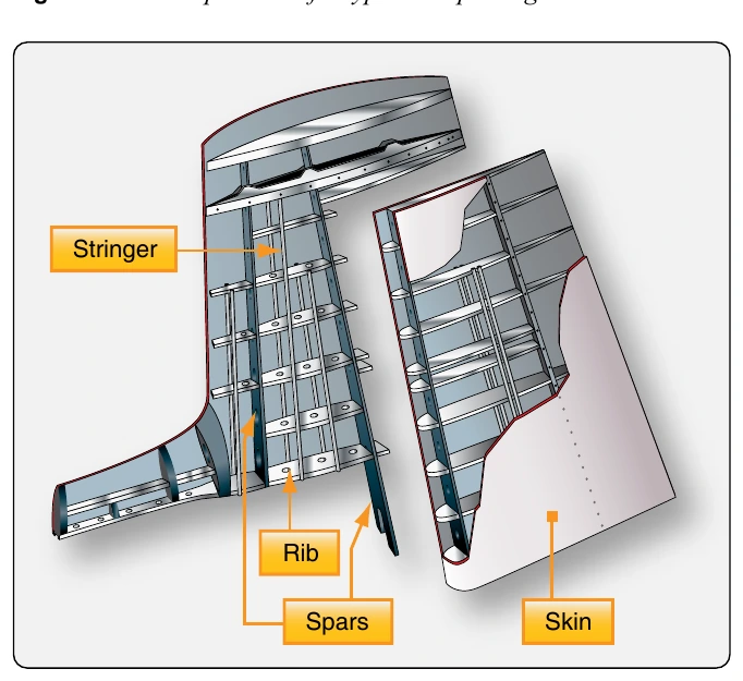
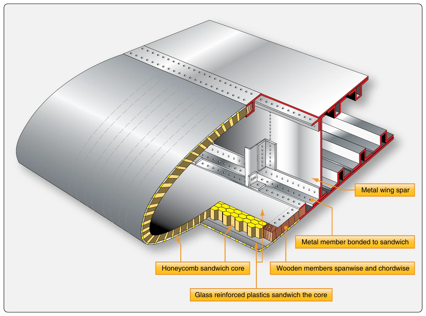
The structure of the stabilizers is very similar to that which is used in wing construction. Figure 1-48 shows a typical vertical stabilizer. Notice the use of spars, ribs, stringers, and skin like those found in a wing. They perform the same functions shaping and supporting the stabilizer and transferring stresses. Bending, torsion, and shear created by air loads in flight pass from one structural member to another. Each member absorbs some of the stress and passes the remainder on to the others. Ultimately, the spar transmits any overloads to the fuselage. A horizontal stabilizer is built the same way.
The rudder and elevator are flight control surfaces that are also part of the empennage discussed in the next section of this chapter.
Flight Control Surfaces
The directional control of a fixed-wing aircraft takes place around the lateral, longitudinal, and vertical axes by means of flight control surfaces designed to create movement about these axes. These control devices are hinged or movable surfaces through which the attitude of an aircraft is controlled during takeoff, flight, and landing. They are usually divided into two major groups: 1) primary or main flight control surfaces and 2) secondary or auxiliary control surfaces.