
Chapter 1
Aircraft Structures
Rudder
The rudder is the primary control surface that causes an aircraft to yaw or move about the vertical axis. This provides directional control and thus points the nose of the aircraft in the direction desired. Most aircraft have a single rudder hinged to the trailing edge of the vertical stabilizer. It is controlled by a pair of foot-operated rudder pedals in the flight deck. When the right pedal is pushed forward, it deflects the rudder to the right which moves the nose of the aircraft to the right. The left pedal is rigged to simultaneously move aft. When the left pedal is pushed forward, the nose of the aircraft moves to the left.
As with the other primary flight controls, the transfer of the movement of the flight deck controls to the rudder varies with the complexity of the aircraft. Many aircraft incorporate the directional movement of the nose or tail wheel into the rudder control system for ground operation. This allows the operator to steer the aircraft with the rudder pedals during taxi when the airspeed is not high enough for the control surfaces to be effective. Some large aircraft have a split rudder arrangement. This is actually two rudders, one above the other. At low speeds, both rudders deflect in the same direction when the pedals are pushed. At higher speeds, one of the rudders becomes inoperative as the deflection of a single rudder is aerodynamically sufficient to maneuver the aircraft.
Dual Purpose Flight Control Surfaces
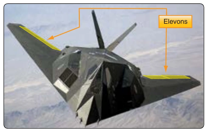
The ailerons, elevators, and rudder are considered conventional primary control surfaces. However, some aircraft are designed with a control surface that may serve a dual purpose. For example, elevons perform the combined functions of the ailerons and the elevator. [Figure 1-57]
A movable horizontal tail section, called a stabilator, is a control surface that combines the action of both the horizontal stabilizer and the elevator. [Figure 1-58] Basically, a stabilator is a horizontal stabilizer that can also be rotated about the horizontal axis to affect the pitch of the aircraft.
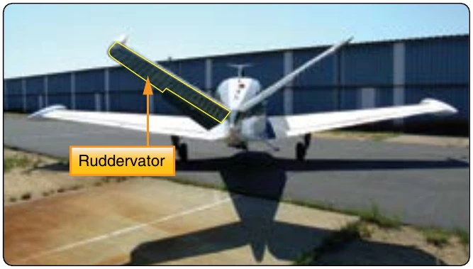
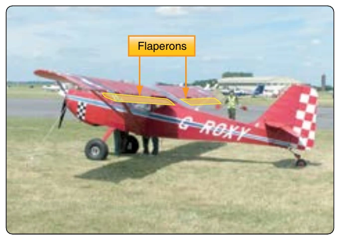
A ruddervator combines the action of the rudder and elevator. [Figure 1-59] This is possible on aircraft with V–tail empennages where the traditional horizontal and vertical stabilizers do not exist. Instead, two stabilizers angle upward and outward from the aft fuselage in a “V” configuration. Each contains a movable ruddervator built into the trailing edge. Movement of the ruddervators can alter the movement of the aircraft around the horizontal and/or vertical axis. Additionally, some aircraft are equipped with flaperons. [Figure 1-60] Flaperons are ailerons which can also act as flaps. Flaps are secondary control surfaces on most wings, discussed in the next section of this chapter.
Secondary or Auxiliary Control Surfaces
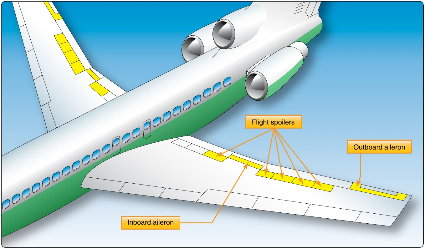
There are several secondary or auxiliary flight control surfaces. Their names, locations, and functions of those for most large aircraft are listed in Figure 1-61.
Flaps
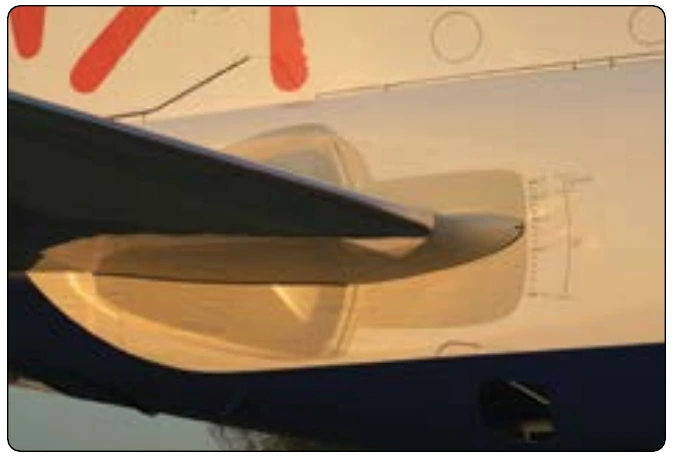
Flaps are found on most aircraft. They are usually inboard on the wings’ trailing edges adjacent to the fuselage. Leading edge flaps are also common. They extend forward and down from the inboard wing leading edge. The flaps are lowered to increase the camber of the wings and provide greater lift and control at slow speeds. They enable landing at slower speeds and shorten the amount of runway required for takeoff and landing. The amount that the flaps extend and the angle they form with the wing can be selected from the flight deck. Typically, flaps can extend up to 45–50°. Figure 1-62 shows various aircraft with flaps in the extended position.
Flaps are usually constructed of materials and with techniques used on the other airfoils and control surfaces of a particular aircraft. Aluminum skin and structure flaps are the norm on light aircraft. Heavy and high-performance aircraft flaps may also be aluminum, but the use of composite structures is also common.
There are various kinds of flaps. Plain flaps form the trailing edge of the wing when the flap is in the retracted position. [Figure 1-63A] The airflow over the wing continues over the upper and lower surfaces of the flap, making the trailing edge of the flap essentially the trailing edge of the wing. The plain flap is hinged so that the trailing edge can be lowered. This increases wing camber and provides greater lift.
A split flap is normally housed under the trailing edge of the wing. [Figure 1-63B] It is usually just a braced flat metal plate hinged at several places along its leading edge. The upper surface of the wing extends to the trailing edge of the flap. When deployed, the split flap trailing edge lowers away from the trailing edge of the wing. Airflow over the top of the wing remains the same. Airflow under the wing now follows the camber created by the lowered split flap, increasing lift.
Fowler flaps not only lower the trailing edge of the wing when deployed but also slide aft, effectively increasing the area of the wing. [Figure 1-63C] This creates more lift via the increased surface area, as well as the wing camber. When stowed, the Fowler flap typically retracts up under the wing trailing edge similar to a split flap. The sliding motion of a Fowler flap can be accomplished with a worm drive and flap tracks.