
Chapter 10
Aircraft Systems
Venturi Tube Systems
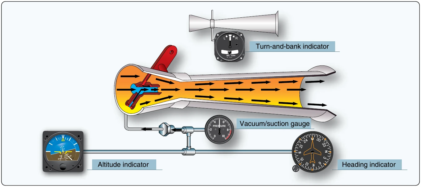
The velocity of the air rushing through a venturi can create sufficient suction to spin instrument gyros. A line is run from the gyro instruments to the throat of the venturi mounted on the outside of the airframe. The low pressure in the venturi tube pulls air through the instruments, spins the gyros, and expels the air overboard through the venturi. This source of gyro power is used on many simple, early aircraft.
A light, single-engine aircraft can be equipped with a 2-inch venturi (2 inches of mercury vacuum capacity) to operate the turn and bank indicator. It can also have a larger 8-inch venturi to power the attitude and heading indicators. Simplified illustrations of these venturi vacuum systems are shown in Figure 10-87. Normally, air going into the instruments is filtered.
The advantages of a venturi as a suction source are its relatively low cost and its simplicity of installation and operation. It also requires no electric power. But there are serious limitations. A venturi is designed to produce the desired vacuum at approximately 100 mph at standard sea level conditions. Wide variations in airspeed or air density cause the suction developed to fluctuate. Airflow can also be hampered by ice that can form on the venturi tube. Additionally, since the rotor does not reach normal operating speed until after takeoff, preflight operational checks of venturi powered gyro instruments cannot be made. For these reasons, alternate sources of vacuum power were developed.
Engine-Driven Vacuum Pump
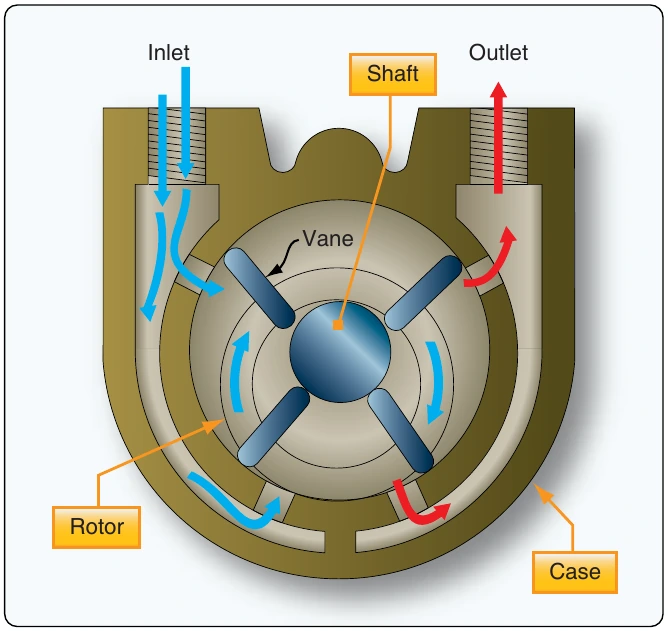
The vane-type engine-driven pump is the most common source of vacuum for gyros installed in general aviation, light aircraft. One type of engine-driven pump is geared to the engine and is connected to the lubricating system to seal, cool, and lubricate the pump. Another commonly used pump is a dry vacuum pump. It operates without external lubrication and installation requires no connection to the engine oil supply. It also does not need the air oil separator or gate check valve found in wet pump systems. In many other respects, the dry pump system and oil lubricated system are the same. [Figure 10-88]
When a vacuum pump develops a vacuum (negative pressure), it also creates a positive pressure at the outlet of the pump. This pressure is compressed air. Sometimes, it is utilized to operate pressure gyro instruments. The components for pressure systems are much the same as those for a vacuum system as listed below. Other times, the pressure developed by the vacuum pump is used to inflate de-ice boots or inflatable seals or it is vented overboard.
An advantage of engine-driven pumps is their consistent performance on the ground and in flight. Even at low engine rpm, they can produce more than enough vacuum so that a regulator in the system is needed to continuously provide the correct suction to the vacuum instruments. As long as the engine operates, the relatively simple vacuum system adequately spins the instrument gyros for accurate indications. However, engine failure, especially on single-engine aircraft, could leave the pilot without attitude and directional information at a critical time. To thwart this shortcoming, often the turn and bank indicator operates with an electrically driven gyro that can be driven by the battery for a short time. Thus, when combined with the aircraft’s magnetic compass, sufficient attitude and directional information is still available.
Multiengine aircraft typically contain independent vacuum systems for the pilot and copilot instruments driven by separate vacuum pumps on each of the engines. Should an engine fail, the vacuum system driven by the still operating engine supplies a full complement of gyro instruments. An interconnect valve may also be installed to connect the failed instruments to the still operational pump.
Typical Pump-Driven System
The following components are found in a typical vacuum system for gyroscopic power supply. A brief description is given of each. Refer to the figures for detailed illustrations.
Air-oil separator—oil and air in the vacuum pump are exhausted through the separator, which separates the oil from the air; the air is vented overboard, and the oil is returned to the engine sump. This component is not present when a dry-type vacuum pump is used. The self-lubricating nature of the pump vanes requires no oil.
Vacuum regulator or suction relief valve—since the system capacity is more than is needed for operation of the instruments, the adjustable vacuum regulator is set for the vacuum desired for the instruments. Excess suction in the instrument lines is reduced when the spring-loaded valve opens to atmospheric pressure. [Figure 10-89]
Gate check valve—prevents possible damage to the instruments by engine backfire that would reverse the flow of air and oil from the pump. [Figure 10-90] Pressure relief valve—since a reverse flow of air from the pump would close both the gate check valve and the suction relief valve, the resulting pressure could rupture the lines. The pressure relief valve vents positive pressure into the atmosphere.
Selector valve—In twin-engine aircraft having vacuum pumps driven by both engines, the alternate pump can be selected to provide vacuum in the event of either engine or pump failure, with a check valve incorporated to seal off the failed pump.