
Chapter 10
Aircraft Systems
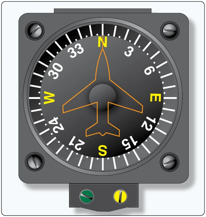
Solutions to the shortcomings of the simple magnetic compass described above have been engineered. The vertical magnetic compass is a variation of the magnetic compass that eliminates the reverse rotation of the compass card just described. By mounting the main indicating magnets of the compass on a shaft rather than a float, through a series of gears, a compass card can be made to turn about a horizontal axis. This allows the numbers for a heading, towards which the pilot wants to turn, to be oriented correctly on the indicating card. In other words, when turning right, increasing numbers are to the right; when turning left, decreasing numbers rotate in from the left. [Figure 10-81]
Many vertical magnetic compasses have also replaced the liquid-filled instrument housing with a dampening cup that uses eddy currents to dampen oscillations. Note that a vertical magnetic compass and a directional gyro look very similar and are often in the lower center position of the instrument panel basic T. Both use the nose of an aircraft as the lubber line against which a rotating compass card is read. Vertical magnetic compasses are characterized by the absence of the hand adjustment knob found on DGs, which is used to align the gyro with a magnetic indication.
Remote Indicating Compass
Magnetic deviation is compensated for by swinging the compass and adjusting compensating magnets in the instrument housing. A better solution to deviation is to remotely locate the magnetic compass in a wing tip or vertical stabilizer where there is very little interference with the earth’s magnetic field. By using a synchro remote indicating system, the magnetic compass float assembly can act as the rotor of the synchro system. As the float mechanism rotates to align with magnetic north in the remotely located compass, a varied electric current can be produced in the transmitter. This alters the magnetic field produced by the coils of the indicator in the flight deck, and a magnetic indication relatively free from deviation is displayed. Many of these systems are of the magnesyn type.
Remote Indicating Slaved Gyro Compass (Flux Gate Compass)
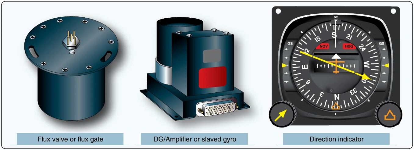
An elaborate and very accurate method of direction indication has been developed that combines the use of a gyro, a magnetic compass, and a remote indicating system. [Figure 10-82] It is called the slaved gyro compass or flux gate compass system. A study of the gyroscopic instruments section of this chapter assists in understanding this device.
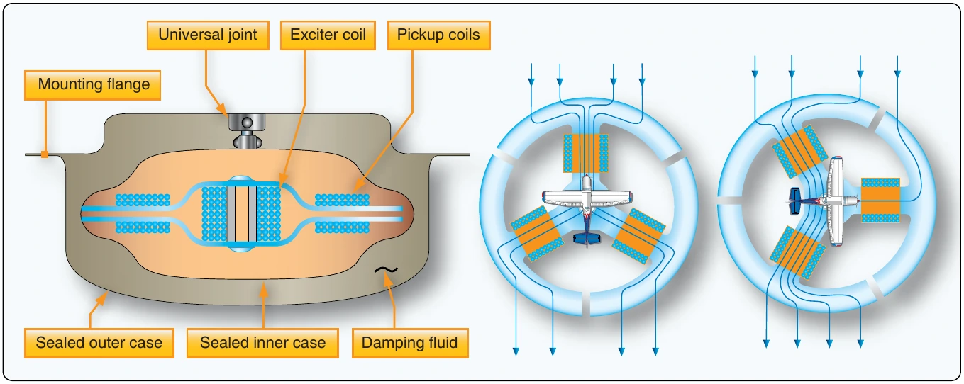
A gyroscopic direction indicator is augmented by magnetic direction information from a remotely located compass. The type of compass used is called a flux valve or flux gate compass. It consists of a very magnetically permeable circular segmented core frame called a spider. The earth’s magnetic field flows through this iron core and varies its distribution through segments of the core as the flux valve is rotated via the movement of the aircraft. Pickup coil windings are located on each of the core’s spider legs that are positioned 120° apart. [Figure 10-83]
The distribution of earth’s magnetic field flowing through the legs is unique for every directional orientation of the aircraft. A coil is placed in the center of the core and is energized by AC current. As the AC flow passes through zero while changing direction, the earth’s magnetic field is allowed to flow through the core. Then, it is blocked or gated as the magnetic field of the core current flow builds to its peak again. The cycle is repeated at the frequency of the AC supplied to the excitation coil. The result is repeated flow and nonflow of the earth’s flux across the pickup coils. During each cycle, a unique voltage is induced in each of the pickup coils reflecting the orientation of the aircraft in the earth’s magnetic field.
The electricity that flows from each of the pickup coils is transmitted out of the flux valve via wires into a second unit. It contains an autosyn transmitter, directional gyro, an amplifier, and a triple wound stator that is similar to that found in the indicator of a synchro system. Unique voltage is induced in the center rotor of this stator which reflects the voltage received from the flux valve pickup coils sent through the stator coils. It is amplified and used to augment the position of the DG. The gyro is wired to be the rotor of an autosyn synchro system, which transmits the position of the gyro into an indicator unit located in the flight deck. [Figure 10-84] In the indicator, a vertical compass card is rotated against a small airplane type lubber line like that in a vertical magnetic compass.
Further enhancements to direction finding systems of this type involving the integration of radio navigation aids are common. The radio magnetic indicator (RMI) is one such variation. [Figure 10-85] In addition to the rotating direction indicator of the slaved gyro compass, it contains two pointers. Each pointer can show the bearing to either a very high frequency (VHF) omnidirectional range (VOR) station or to a non-directional automatic direction finder (ADF) beacon. These and other radio navigation aids are discussed further in the communications and navigation chapter of this handbook. It should also be noted that integration of slaved gyro direction indicating system information into auto-pilot systems is also possible.
Solid State Magnetometers
Solid state magnetometers are used on many modern aircraft. They have no moving parts and are extremely accurate. Tiny layered structures react to magnetism on a molecular level resulting in variations in electron activity. These low power consuming devices can sense not only the direction to the earth’s magnetic poles, but also the angle of the flux field. They are free from oscillation that plagues a standard magnetic compass. They feature integrated processing algorithms and easy integration with digital systems. [Figure 10-86]
Sources of Power for Gyroscopic Instruments
Gyroscopic instruments are essential instruments used on all aircraft. They provide the pilot with critical attitude and directional information and are particularly important while flying under IFR. The sources of power for these instruments can vary. The main requirement is to spin the gyroscopes at a high rate of speed. Originally, gyroscopic instruments were strictly vacuum driven. A vacuum source pulled air across the gyro inside the instruments to make the gyros spin. Later, electricity was added as a source of power. The turning armature of an electric motor doubles as the gyro rotor. In some aircraft, pressure, rather than vacuum, is used to induce the gyro to spin. Various systems and powering configurations have been developed to provide reliable operation of the gyroscopic instruments.
Vacuum Systems
Vacuum systems are very common for driving gyro instruments. In a vacuum system, a stream of air directed against the rotor vanes turns the rotor at high speed. The action is similar to a water wheel. Air at atmospheric pressure is first drawn through a filter(s). It is then routed into the instrument and directed at vanes on the gyro rotor. A suction line leads from the instrument case to the vacuum source. From there, the air is vented overboard. Either a venturi or a vacuum pump can be used to provide the vacuum required to spin the rotors of the gyro instruments.
The amount of vacuum required for instrument operation is usually between 3½ inches to 4½ inches of mercury. It is usually adjusted by a vacuum relief valve located in the supply line. Some turn-and-bank indicators require a lower vacuum setting. This can be obtained through the use of an additional regulating valve in the turn and bank vacuum supply line.