Chapter 10
Aircraft Systems
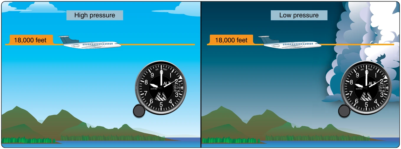
The term “pressure altitude” is used to describe the indication an altimeter gives when 29.92 is set in the Kollsman window. When flying in U.S. airspace above 18,000 feet mean sea level (MSL), pilots are required to set their altimeters to 29.92. With all aircraft referencing this standard pressure level, vertical separation between aircraft assigned to different altitudes by ATC should be assured. This is the case if all altimeters are functioning properly and pilots hold their assigned altitudes. The actual, or true altitude, is less important than keeping aircraft from colliding, which is accomplished by all aircraft above 18,000 feet referencing the same barometric pressure (29.92 “Hg) on their altimeters. [Figure 10-35]
Temperature also affects the accuracy of an altimeter. The aneroid diaphragms used in altimeters are usually made of metal. Their elasticity changes as their temperature changes. This can lead to a false indication, especially at high altitudes when the ambient air is very cold. A bimetallic compensating device is built into many sensitive altimeters to correct for varying temperature. Figure 10-33 shows one such device on a drum-type altimeter.
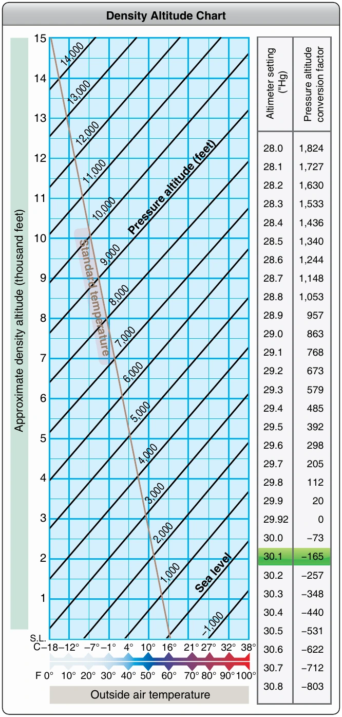
Temperature also affects air density, which has great impact on the performance of an aircraft. Although this does not cause the altimeter to produce an errant reading, flight crews must be aware that performance changes with temperature variations in the atmosphere. The term density altitude describes altitude corrected for nonstandard temperature. That is, the density altitude is the standard day altitude (pressure altitude) at which an aircraft would experience similar performance as it would on the non-standard day currently being experienced. For example, on a very cold day, the air is denser than on a standard day, so an aircraft performs as though it is at a lower altitude. The density altitude is lower that day. On a very hot day, the reverse is true, and an aircraft performs as though it were at a higher elevation where the air is less dense. The density altitude is higher that day.
Conversion factors and charts have been produced so pilots can calculate the density altitude on any particular day. Inclusion of nonstandard air pressure due to weather systems and humidity can also be factored. So, while the effects of temperature on aircraft performance do not cause an altimeter to indicate falsely, an altimeter indication can be misleading in terms of aircraft performance if these effects are not considered. [Figure 10-36]
Other factors can cause an inaccurate altimeter indication. Scale error is a mechanical error whereby the scale of the instrument is not aligned so the altimeter pointers indicate correctly. Periodic testing and adjustment by trained technicians using calibrated equipment ensures scale error is kept to a minimum.
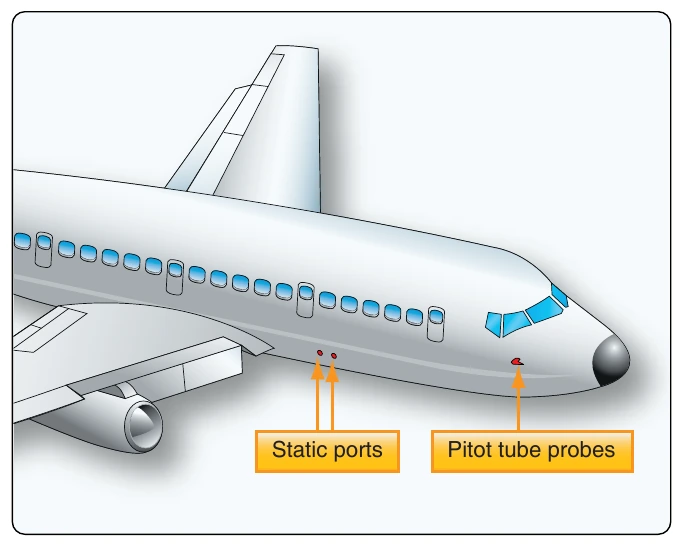
The pressure altimeter is connected to the pitot-static system and must receive an accurate sample of ambient air pressure to indicate the correct altitude. Position error, or installation error, is that inaccuracy caused by the location of the static vent that supplies the altimeter. While every effort is made to place static ports in undisturbed air, airflow over the airframe changes with the speed and attitude of the aircraft. The amount of this air pressure collection error is measured in test flights, and a correction table showing the variances can be included with the altimeter for the pilot’s use. Normally, location of the static vents is adjusted during these test flights so that the position error is minimal. [Figure 10-37] Position error can be removed by the ADC in modern aircraft, so the pilot need not be concerned about this inaccuracy.
Static system leaks can affect the static air input to the altimeter or ADC resulting in inaccurate altimeter indications. It is for this reason that static system maintenance includes leak checks every 24 months, regardless of whether any discrepancy has been noticed. See the instrument maintenance section toward the end of this chapter for further information on this mandatory check. It should also be understood that analog mechanical altimeters are mechanical devices that often reside in a hostile environment. The significant vibration and temperature range swings encountered by the instruments and the pitot static system (i.e., the tubing connections and fittings) can sometime create damage or a leak, leading to instrument malfunction. Proper care upon installation is the best preventive action. Periodic inspection and testing can also assure integrity.
The mechanical nature of the analog altimeter’s diaphragm pressure measuring apparatus has limitations. The diaphragm itself is only so elastic when responding to static air pressure changes. Hysteresis is the term for when the material from which the diaphragm is made takes a set during long periods of level flight. If followed by an abrupt altitude change, the indication lags or responds slowly while expanding or contracting during a rapid altitude change. While temporary, this limitation does cause an inaccurate altitude indication.
It should be noted that many modern altimeters are constructed to integrate into flight control systems, autopilots, and altitude monitoring systems, such as those used by ATC. The basic pressure-sensing operation of these altimeters is the same, but a means for transmitting the information is added.
Vertical Speed Indicator
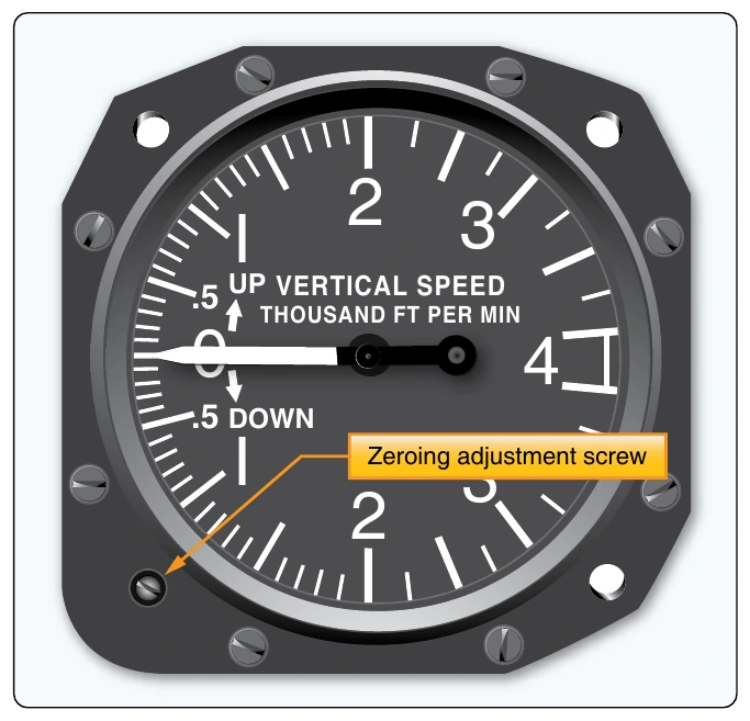
An analog vertical speed indicator (VSI) may also be referred to as a vertical velocity indicator (VVI), or rate-of-climb indicator. It is a direct reading, differential pressure gauge that compares static pressure from the aircraft’s static system directed into a diaphragm with static pressure surrounding the diaphragm in the instrument case. Air is free to flow unrestricted in and out of the diaphragm but is made to flow in and out of the case through a calibrated orifice. A pointer attached to the diaphragm indicates zero vertical speed when the pressure inside and outside the diaphragm are the same. The dial is usually graduated in 100s of feet per minute. A zeroing adjustment screw, or knob, on the face of the instrument is used to center the pointer exactly on zero while the aircraft is on the ground. [Figure 10-38]
As the aircraft climbs, the unrestricted air pressure in the diaphragm lowers as the air becomes less dense. The case air pressure surrounding the diaphragm lowers more slowly, having to pass through the restriction created by the orifice. This causes unequal pressure inside and outside the diaphragm, which in turn causes the diaphragm to contract a bit and the pointer indicates a climb. The process works in reverse for an aircraft in a descent. If a steady climb or descent is maintained, a steady pressure differential is established between the diaphragm and case pressure surrounding it, resulting in an accurate indication of the rate of climb via graduations on the instrument face. [Figure 10-39]
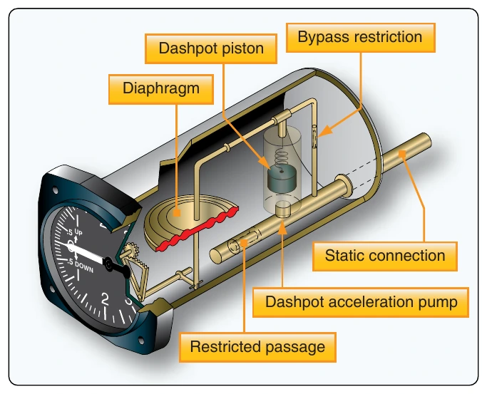
A shortcoming of the rate-of-climb mechanism as described is that there is a lag of six to nine seconds before a stable differential pressure can be established that indicates the actual climb or descent rate of the aircraft. An instantaneous vertical speed indicator (IVSI) has a built-in mechanism to reduce this lag. A small, lightly sprung dashpot, or piston, reacts to the direction change of an abrupt climb or descent. As this small accelerometer does so, it pumps air into or out of the diaphragm, hastening the establishment of the pressure differential that causes the appropriate indication. [Figure 10-40]
Gliders and lighter-than-air aircraft often make use of a variometer. This is a differential VSI that compares static pressure with a known pressure. It is very sensitive and gives an instantaneous indication. It uses a rotating vane with a pointer attached to it. The vane separates two chambers. One is connected to the aircraft’s static vent or is open to the atmosphere. The other is connected to a small reservoir inside the instrument that is filled to a known pressure. As static air pressure increases, the pressure in the static air chamber increases and pushes against the vane. This rotates the vane and pointer, indicating a descent since the static pressure is now greater than the set amount in the chamber with reservoir pressure. During a climb, the reservoir pressure is greater than the static pressure; the vane is pushed in the opposite direction, causing the pointer to rotate and indicate a climb. [Figure 10-41]
The rate-of-climb indication in a digitally displayed instrument system is computed from static air input to the ADC. An aneroid, or solid-state pressure sensor, continuously reacts to changes in static pressure. The digital clock within the computer replaces the calibrated orifice found on an analog instrument. As the static pressure changes, the computer’s clock can be used to develop a rate for the change. Using the known lapse rate conversion for air pressure as altitude increases or decreases, a figure for climb or descent in fpm can be calculated and sent to the flight deck. The vertical speed is often displayed near the altimeter information on the primary flight display. [Figure 10-34]