Chapter 10
Aircraft Systems
Pitot Tubes & Static Vents
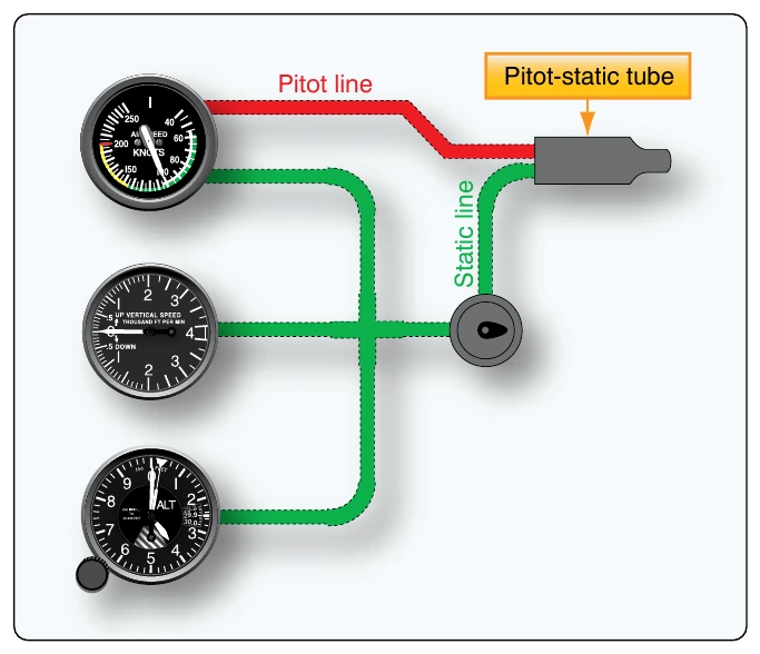
On simple aircraft, this may consist of a pitot-static system head or pitot tube with impact and static air pressure ports and leak-free tubing connecting these air pressure pick-up points to the instruments that require the air for their indications. The altimeter, airspeed indicator, and vertical speed indicator are the three most common pitot-static instruments. Figure 10-22 illustrates a simple pitot-static system connected to these three instruments. All three instruments are connected to the static pressure system. The airspeed indicator is additionally connected to the pitot pressure system. The altimeter is connected to the static pressure system.
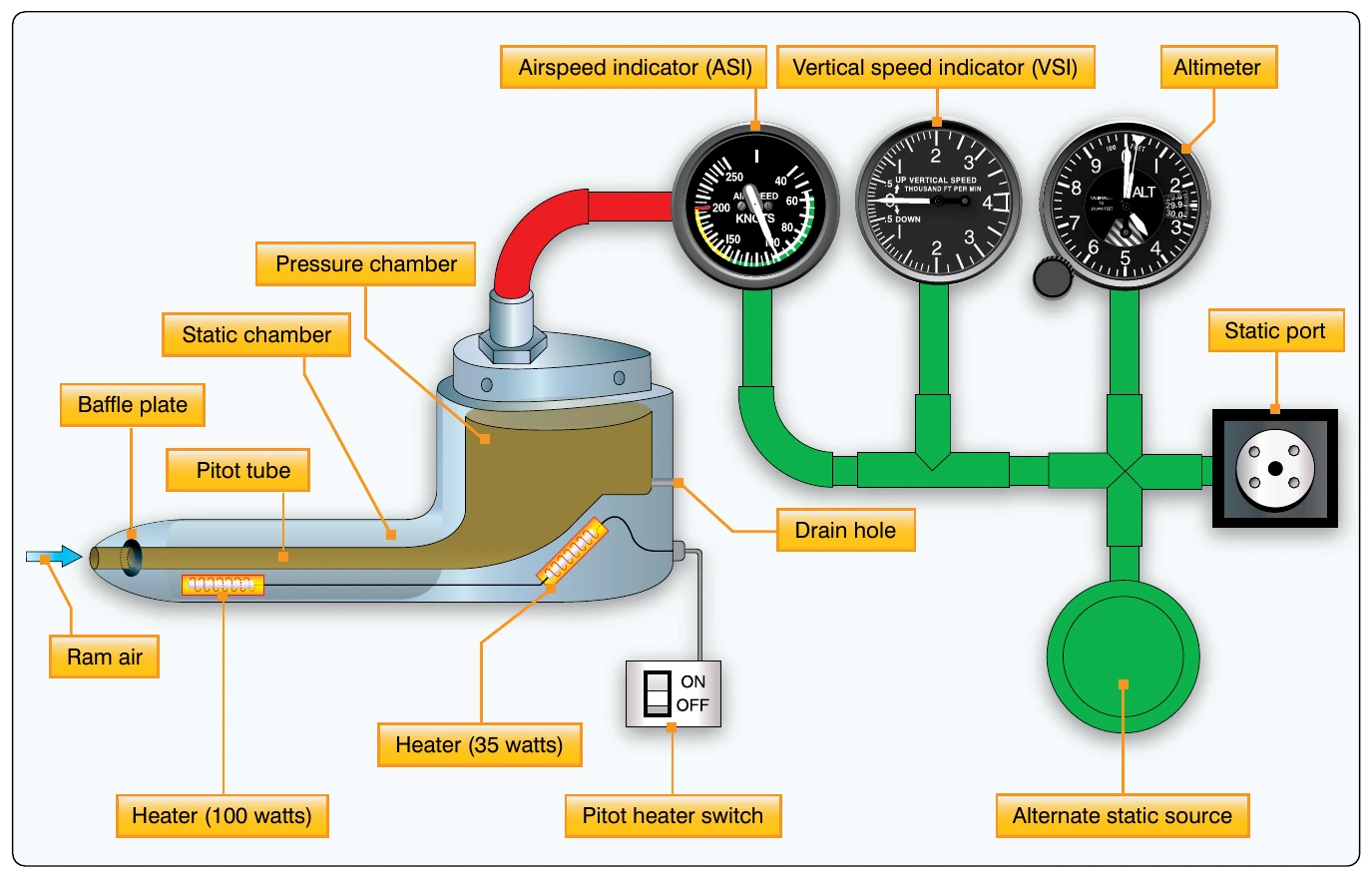
A pitot tube is open and faces into the airstream to receive the full force of the impact air pressure as the aircraft moves forward. This air passes through a baffled plate designed to protect the system from moisture and dirt entering the tube. Below the baffle, a drain hole is provided, allowing moisture to escape. The ram air is directed aft to a chamber in the shark fin of the assembly. An upright tube, or riser, leads this pressurized air out of the pitot assemble to the airspeed indicator.
The aft section of the pitot tube is equipped with small holes on the top and bottom surfaces that are designed to collect air pressure that is at atmospheric pressure in a static, or still, condition. The static section also contains a riser tube and the air is run out the pitot assembly through tubes and is connected to the altimeter, the airspeed indicator, and the vertical speed indicator. [Figure 10-23]
Many pitot-static tube heads contain heating elements to prevent icing during flight. The pilot can send electric current to the element with a switch in the flight deck when ice-forming conditions exist. The pitot tube heat switch may be wired so that when the ignition switch is turned off when the aircraft is shut down, a pitot tube heater inadvertently left on does not continue to draw current and drain the battery. Caution should be exercised when near the pitot tube, as these heating elements make the tube too hot to be touched without receiving a burn.
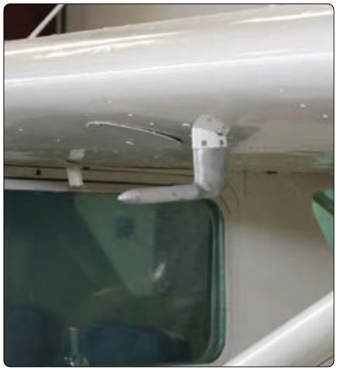
The pitot-static tube is mounted on the outside of the aircraft at a point where the air is least likely to be turbulent. It is pointed in a forward direction parallel to the aircraft’s line of flight. The location may vary. Some are on the nose of the fuselage and others may be located on a wing. A few may even be found on the empennage. Various designs exist but the function remains the same, to capture impact air pressure and static air pressure and direct them to the proper instruments. [Figure 10-24]
Most aircraft equipped with a pitot-static tube have an alternate source of static air pressure provided for emergency use. The pilot may select the alternate with a switch in the flight deck should it appear the flight instruments are not providing accurate indications. On low-flying unpressurized aircraft, the alternate static source may simply be air from the cabin. [Figure 10-25] On pressurized aircraft, cabin air pressure may be significantly different than the outside ambient air pressure. If used as an alternate source for static air, instrument indications would be grossly inaccurate. In this case, multiple static vent pickup points are employed. All are located on the outside of the aircraft and plumbed so the pilot can select which source directs air into the instruments.
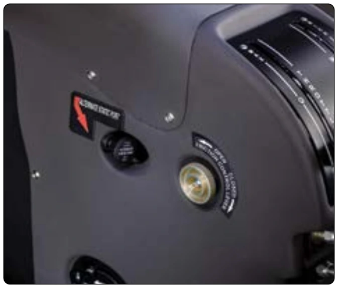
On electronic flight displays, the choice is made for which source is used by the computer or by the flight crew.
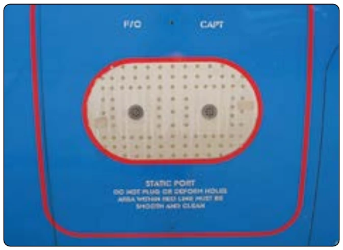
Another type of pitot-static system provides for the location of the pitot and static sources at separate positions on the aircraft. The pitot tube in this arrangement is used only to gather ram air pressure. Separate static vents are used to collect static air pressure information. Usually, these are located flush on the side of the fuselage. [Figure 10-26] There may be two or more vents. A primary and alternate source vent is typical, as well as separate dedicated vents for the pilot and first officer’s instruments. Also, two primary vents may be located on opposite sides of the fuselage and connected with Y tubing for input to the instruments. This is done to compensate for any variations in static air pressure on the vents due to the aircraft’s attitude. Regardless of the number and location of separate static vents, they may be heated as well as the separate ram air pitot tube to prevent icing.
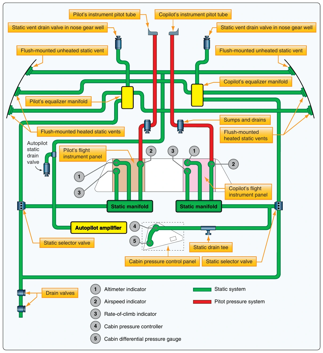
The pitot-static systems of complex, multiengine, and pressurized aircraft can be elaborate. Additional instruments, gauges, the autopilot system, and computers may need pitot and static air information. Figure 10-27 shows a pitot-static system for a pressurized multiengine aircraft with dual analog instrument panels in the flight deck. The additional set of flight instruments for the copilot alters and complicates the pitot-static system plumbing. Additionally, the autopilot system requires static pressure information, as does the cabin pressurization unit. Separate heated sources for static air pressure are taken from both sides of the airframe to feed independent static air pressure manifolds; one each for the pilot’s flight instruments and the copilot’s flight instruments. This is designed to ensure that there is always one set of flight instruments operable in case of a malfunction.
Air Data Computers (ADC) & Digital Air Data Computers (DADC)
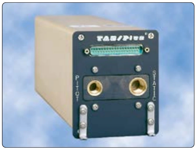
High performance and jet transport category aircraft pitot-static systems may be more complicated. These aircraft frequently operate at high altitude where the ambient temperature can exceed 50 °F below zero. The compressibility of air is also altered at high speeds and at high altitudes. Airflow around the fuselage changes, making it difficult to pick up consistent static pressure inputs. The pilot must compensate for all factors of air temperature and density to obtain accurate indications from instruments. While many analog instruments have compensating devices built into them, the use of an air data computer (ADC) is common for these purposes on high-performance aircraft. Moreover, modern aircraft utilize digital air data computers (DADC). The conversion of sensed air pressures into digital values makes them more easily manipulated by the computer to output accurate information that has compensated for the many variables encountered. [Figure 10-28]
Essentially, all pressures and temperatures captured by sensors are fed into theADC.Analog units utilize transducers to convert these to electrical values and manipulate them in various modules containing circuits designed to make the proper compensations for use by different instruments and systems. A DADC usually receives its data in digital format. Systems that do not have digital sensor outputs will first convert inputs into digital signals via an analog-to-digital converter. Conversion can take place inside the computer or in a separate unit designed for this function. Then, all calculation and compensations are performed digitally by the computer. Outputs from the ADC are electric to drive servo motors or for use as inputs in pressurization systems, flight control units, and other systems. DADC outputs are distributed to these same systems and the flight deck display using a digital data bus.