
Chapter 11
Communication & Navigation
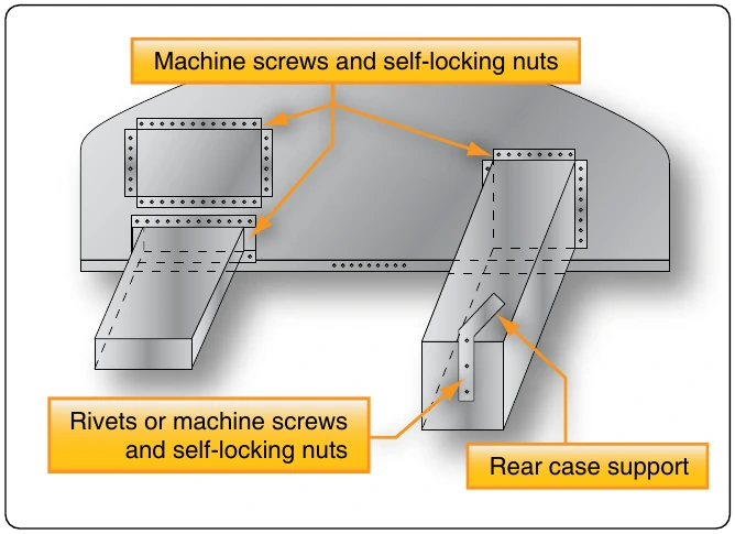
The performance and service life of most avionics equipment is seriously limited by excessive ambient temperatures. High performance aircraft with avionics equipment racks typically route air-conditioned air over the avionics to keep them cool. It is also common for non-air conditioned aircraft to use a blower or scooped ram air to cool avionics installations. When adding a unit to an aircraft, the installation should be planned so that it can dissipate heat readily. In some installations, it may be necessary to produce airflow over the new equipment either with a blower or through the use of routed ram air. Be sure that proper baffling is used to prevent water from reaching any electronics when ducting outside air. The presence of water in avionics equipment areas promotes rapid deterioration of the exposed components and could lead to failure.
Vibration Isolation
Vibration is a continued motion by an oscillating force. The amplitude and frequency of vibration of the aircraft structure will vary considerably with the type of aircraft. Avionics equipment is sensitive to mechanical shock and vibration and is normally shock mounted to provide some protection against in-flight vibration and landing shock.
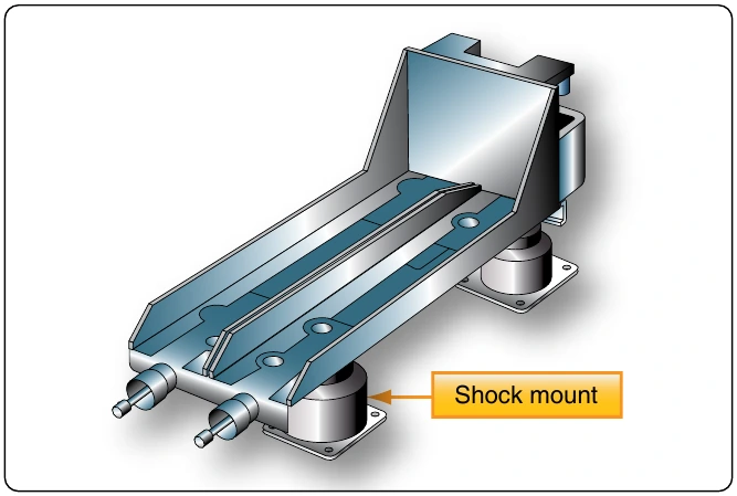
Special shock mounted racks are often used to isolate avionics equipment from vibrating structure. [Figure 11-158] Such mounts should provide adequate isolation over the entire range of expected vibration frequencies. When installing shock mounts, assure that the equipment weight does not exceed the weight-carrying capabilities of the mounts. Radio equipment installed on shock mounts must have sufficient clearance from surrounding equipment and structure to allow for normal swaying of the equipment.
Radios installed in instrument panels do not ordinarily require vibration protection since the panel itself is usually shock mounted. However, make certain that the added weight of any added equipment can be safely carried by the existing mounts. In some cases, it may be necessary to install larger capacity mounts or to increase the number of mounting points. Periodic inspection of the shock mounts is required, and defective mounts should be replaced with the proper type. The following factors to observe during the inspection are:
- Deterioration of the shock-absorbing material;
- Stiffness and resiliency of the material; and
- Overall rigidity of the mount.
If the mount is too stiff, it may not provide adequate protection against the shock of landing. If the shock mount is not stiff enough, it may allow prolonged vibration following an initial shock.
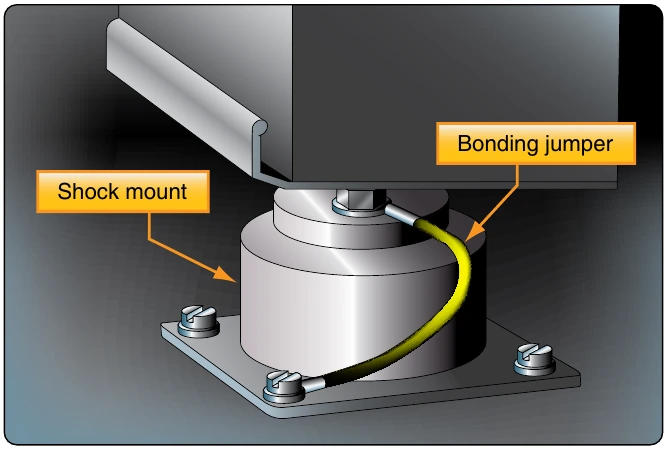
Shock-absorbing materials commonly used in shock mounts are usually electrical insulators. For this reason, each electronic unit mounted with shock mounts must be electrically bonded to a structural member of the aircraft to provide a current path to ground. This is accomplished by secure attachment of a tinned copper wire braid from the component, across the mount, to the aircraft structure as shown in Figure 11-159. Occasional bonding is accomplished with solid aluminum or copper material where a short flexible strap is not possible.
Reducing Radio Interference
Suppression of unwanted electromagnetic fields and electrostatic interference is essential on all aircraft. In communication radios, this is noticeable as audible noise. In other components, the effects may not be audible but pose a threat to proper operation. Large discharges of static electricity can permanently damage the sensitive solid-state microelectronics found in nearly all modern avionics.
Shielding
Many components of an aircraft are possible sources of electrical interference which can deteriorate the performance and reliability of avionics components. Rotating electrical devices, switching devices, ignition systems, propeller control systems, AC power lines, and voltage regulators all produce potential damaging fields. Shielding wires to electric components and ignition systems dissipates radio frequency noise energy. Instead of radiating into space, the braided conductive shielding guides unwanted current flows to ground. To prevent the build-up of electrical potential, all electrical components should also be bonded to the aircraft structure (ground).
Isolation
Isolation is another practical method of radio frequency suppression to prevent interference. This involves separating the source of the noise from the input circuits of the affected equipment. In some cases, noise in a receiver may be entirely eliminated simply by moving the antenna lead-in wire just a few inches away from a noise source. On other occasions, when shielding and isolation are not effective, a filter may need to be installed in the input circuit of an affected component.
Bonding
The aircraft surface can become highly charged with static electricity while in flight. Measures are required to eliminate the build-up and radiation of unwanted electrical charges. One of the most important measures taken to eliminate unwanted electrical charges which may damage or interfere with avionics equipment is bonding. Charges flowing in paths of variable resistance due to such causes as intermittent contact from vibration or the movement of a control surface produce electrical disturbances (noise) in avionics. Bonding provides the necessary electric connection between metallic parts of an aircraft to prevent variable resistance in the airframe. It provides a low-impedance ground return which minimizes interference from static electricity charges.
All metal parts of the aircraft should be bonded to prevent the development of electrical potential build-up. Bonding also provides the low resistance return path for single-wire electrical systems. Bonding jumpers and clamps are examples of bonding connectors. Jumpers should be as short as possible. Be sure finishes are removed in the contact area of a bonding device so that metal-to-metal contact exists. Resistance should not exceed.003 ohm. When a jumper is used only to reduce radio frequency noise and is not for current carrying purposes, a resistance of 0.01 ohm is satisfactory.