
Chapter 11
Communication & Navigation
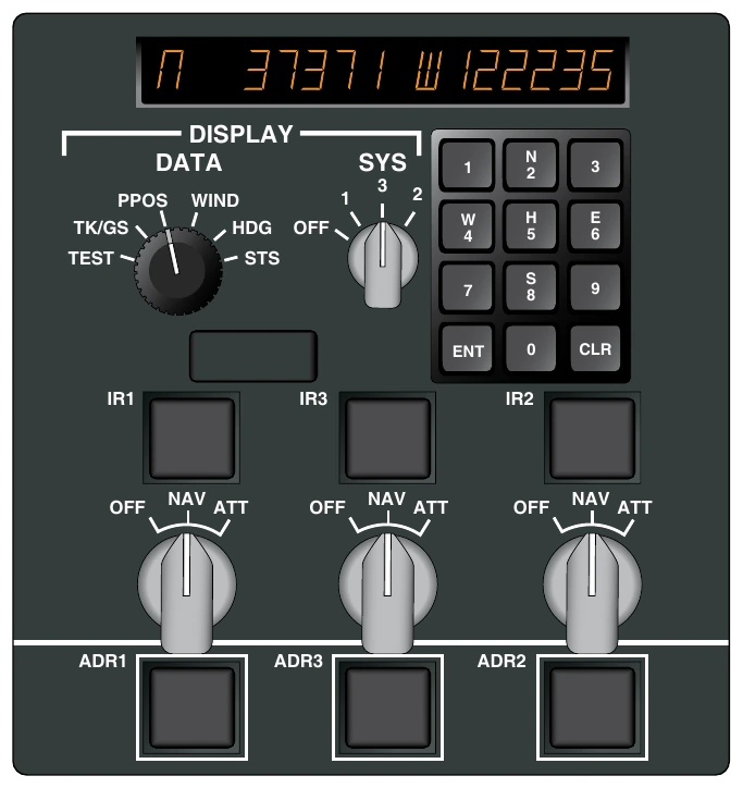
INS is integrated into an airliner’s flight management system and automatic flight control system. Waypoints can be entered for a predetermined flightpath and the INS will guide the aircraft to each waypoint in succession. Integration with other NAV aids is also possible to ensure continuous correction and improved accuracy but is not required.
Modern INS systems are known as IRS. They are completely solid-state units with no moving parts. Three-ring, laser gyros replace the mechanical gyros in the older INS platform systems. This eliminates precession and other mechanical gyro shortcomings. The use of three solid-state accelerometers, one for each plane of movement, also increases accuracy. The accelerometer and gyro output are input to the computer for continuous calculation of the aircraft’s position.
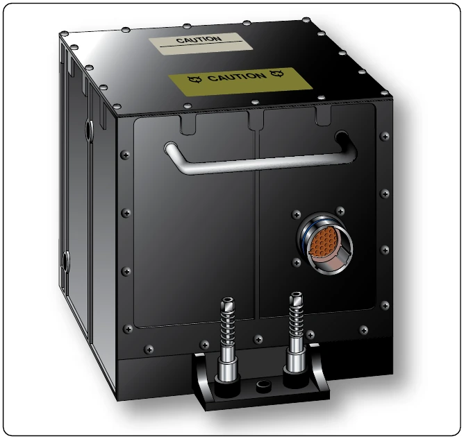
The most modern IRS integration is the satellite GPS. The GPS is extremely accurate in itself. When combined with IRS, it creates one of the most accurate navigation systems available. The GPS is used to initialize the IRS so the pilot no longer needs to do so. GPS also feeds data into the IRS computer to be used for error correction. Occasional service interruptions and altitude inaccuracies of the GPS system pose no problem for IRS/GPS. The IRS functions continuously and is completely self-contained within the IRS unit. Should the GPS falter, the IRS portion of the system continues without it. The latest electronic technology has reduced the size and weight of INS/IRS avionics units significantly. Figure 11-156 shows a modern micro-IRS unit that measures approximately six inches on each side.
Aircraft Communication Addressing & Reporting System (ACARS)
ACARS is a two-way communication link between an airliner in flight and the airline’s main ground facilities. Data is collected in the aircraft by digital sensors and is transmitted to the ground facilities. Replies from the ground may be printed out so the appropriate flight crewmember can have a hard copy of the response.
Installation of Communication & Navigation Equipment
Approval of New Avionics Equipment Installations
Most of the avionics equipment discussed in this chapter is only repairable by the manufacturer or FAA-certified repair stations that are licensed to perform specific work. The airframe technician; however, must competently remove, install, inspect, maintain, and troubleshoot these ever increasingly complicated electronic devices and systems. It is imperative to follow all equipment and airframe manufacturers’instruction when dealing with an aircraft’s avionics.
The revolution to GPS navigation and the pace of modern electronic development results in many aircraft owner operators upgrading flight decks with new avionics. The aircraft technician must only perform airworthy installations. The avionics equipment to be installed must be a TSO’d device that is approved for installation in the aircraft in question. The addition of a new piece of avionics equipment and/or its antenna is a minor alteration if previously approved by the airframe manufacturer. A certificated airframe technician is qualified to perform the installation and return the aircraft to service. The addition of new avionics not on the aircraft’s approved equipment list is considered a major alteration and requires an FAA Form 337 to be completed. A technician with an inspection authorization is required to complete the approval for return to service following a major alteration and to sign the corresponding approval for return to service block on Form 337.
Most new avionics installations are approved and performed under an STC. The equipment manufacturer supplies a list of aircraft on which the equipment has been approved for installation. The STC includes thorough installation and maintenance instructions which the technician must follow. Regardless, if not on the aircraft’s original equipment list, the STC installation is considered a major alteration and an FAA Form 337 must be filed. The STC is referenced as the required approved data.
Occasionally, an owner/operator or technician wishes to install an electronic device in an aircraft that has no STC for the model aircraft in question. A field approval and a Form 337 must be filed on which it must be shown that the installation will be performed in accordance with approved data.
Considerations
There are many factors which the technician must consider prior to altering an aircraft by the addition of avionics equipment. These factors include the space available, the size and weight of the equipment, and previously accomplished alterations. The power consumption of the added equipment must be considered to calculate and determine the maximum continuous electrical load on the aircraft’s electrical system. Each installation should also be planned to allow easy access for inspection, maintenance, and exchange of units.
The installation of avionics equipment is partially mechanical, involving sheet metal work to mount units, racks, antennas, and controls. Routing of the interconnecting wires, cables, antenna leads, etc. is also an important part of the installation process. When selecting a location for the equipment, use the area(s) designated by the airframe manufacturer or the STC. If such information is not available, select a location for installation that will carry the loads imposed by the weight of the equipment, and which is capable of withstanding the additional inertia forces.
If an avionics device is to be mounted in the instrument panel and no provisions have been made for such an installation, ensure that the panel is not a primary structure prior to making any cutouts. To minimize the load on a stationary instrument panel, a support bracket may be installed between the rear of the electronics case or rack and a nearby structural member of the aircraft. [Figure 11-157]
Avionics radio equipment must be securely mounted to the aircraft. All mounting bolts must be secured by locking devices to prevent loosening from vibration. Adequate clearance between all units and adjacent structure must be provided to prevent mechanical damage to electric wiring or to the avionic equipment from vibration, chafing, or landing shock.
Do not locate avionics equipment and wiring near units containing combustible fluids. When separation is impractical, install baffles or shrouds to prevent contact of the combustible fluids with any electronic equipment in the event of plumbing failure.