
Chapter 12
Hydraulic & Pneumatic Power Systems
Pressure relief valves cannot be used as pressure regulators in large hydraulic systems that depend on engine-driven pumps for the primary source of pressure because the pump is constantly under load and the energy expended in holding the pressure relief valve off its seat is changed into heat. This heat is transferred to the fluid and, in turn, to the packing rings, causing them to deteriorate rapidly. Pressure relief valves, however, may be used as pressure regulators in small, low-pressure systems or when the pump is electrically driven and is used intermittently.
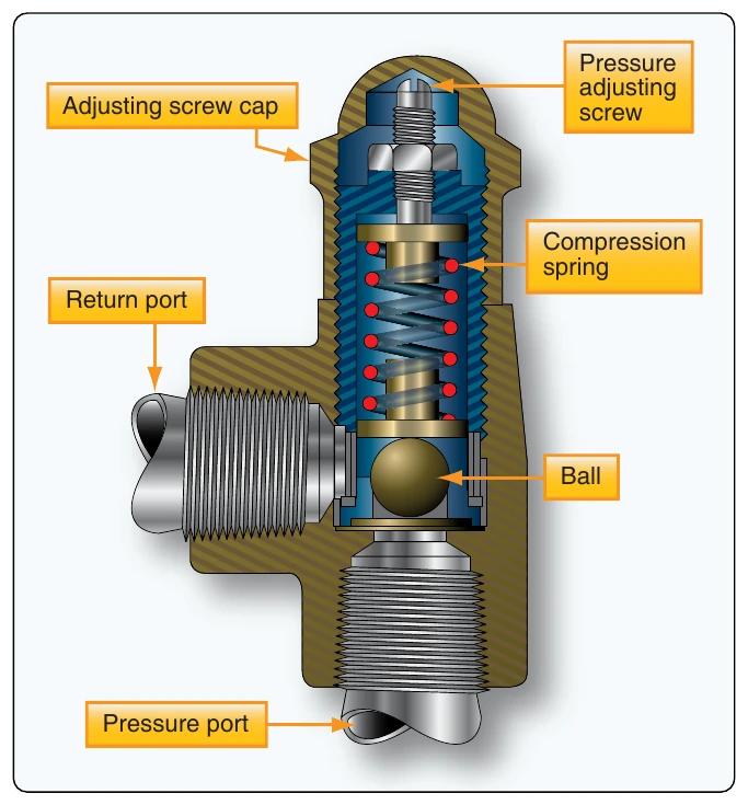
Pressure relief valves may be used as:
- System relief valve—the most common use of the pressure relief valve is as a safety device against the possible failure of a pump compensator or other pressure regulating device. All hydraulic systems that have hydraulic pumps incorporate pressure relief valves as safety devices.
- Thermal relief valve—the pressure relief valve is used to relieve excessive pressures that may exist due to thermal expansion of the fluid. They are used where a check valve or selector valve prevents pressure from being relieved through the main system relief valve. Thermal relief valves are usually smaller than system relief valves. As pressurized fluid in the line in which it is installed builds to an excessive amount, the valve poppet is forced off its seat. This allows excessive pressurized fluid to flow through the relief valve to the reservoir return line. When system pressure decreases to a predetermined pressure, spring tension overcomes system pressure and forces the valve poppet to the closed position.
Pressure Regulators
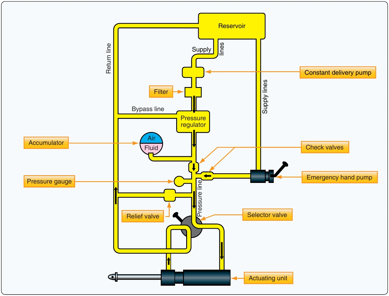
The term pressure regulator is applied to a device used in hydraulic systems that are pressurized by constant-delivery-type pumps. One purpose of the pressure regulator is to manage the output of the pump to maintain system operating pressure within a predetermined range. The other purpose is to permit the pump to turn without resistance (termed unloading the pump) at times when pressure in the system is within normal operating range. The pressure regulator is located in the system so that pump output can get into the system pressure circuit only by passing through the regulator. The combination of a constant-delivery-type pump and the pressure regulator is virtually the equivalent of a compensator-controlled, variable-delivery-type pump. [Figure 12-45]
Pressure Reducers
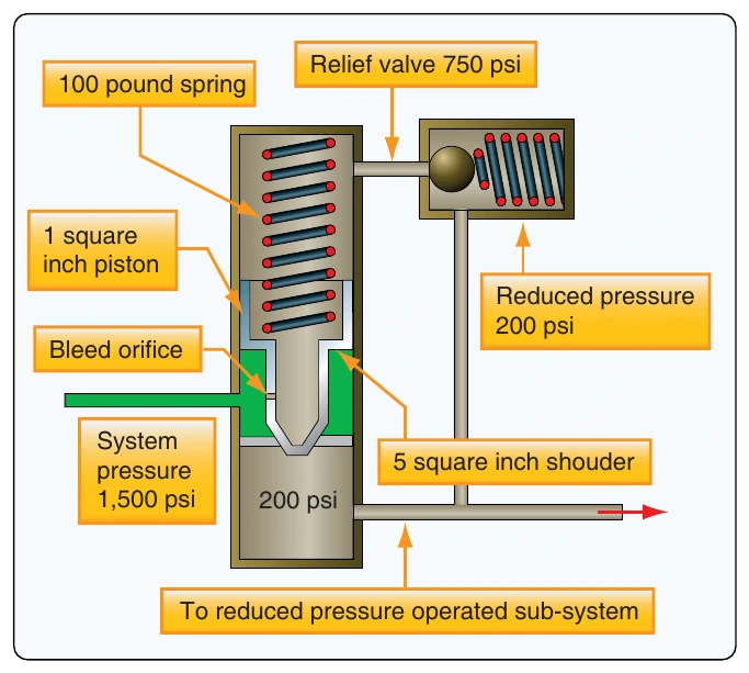
Pressure reducing valves are used in hydraulic systems where it is necessary to lower the normal system operating pressure by a specified amount. Pressure reducing valves provide a steady pressure into a system that operates at a lower pressure than the supply system. A reducing valve can normally be set for any desired downstream pressure within the design limits of the valve. Once the valve is set, the reduced pressure is maintained regardless of changes in supply pressure (as long as the supply pressure is at least as high as the reduced pressure desired) and regardless of the system load, if the load does not exceed the designed capacity of the reducer. [Figure 12-46]
Shuttle Valves
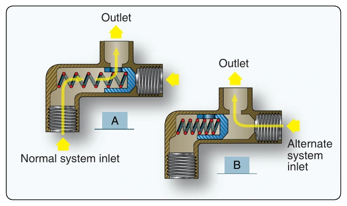
In certain fluid power systems, the supply of fluid to a subsystem must be from more than one source to meet system requirements. In some systems, an emergency system is provided as a source of pressure in the event of normal system failure. The emergency system usually actuates only essential components. The main purpose of the shuttle valve is to isolate the normal system from an alternate or emergency system. It is small and simple; yet, it is a very important component. [Figure 12-47] The housing contains three ports—normal system inlet, alternate or emergency system inlet, and outlet. A shuttle valve used to operate more than one actuating unit may contain additional unit outlet ports.
Enclosed in the housing is a sliding part called the shuttle. Its purpose is to seal off one of the inlet ports. There is a shuttle seat at each inlet port. When a shuttle valve is in the normal operation position, fluid has a free flow from the normal system inlet port, through the valve, and out through the outlet port to the actuating unit. The shuttle is seated against the alternate system inlet port and held there by normal system pressure and by the shuttle valve spring. The shuttle remains in this position until the alternate system is activated. This action directs fluid under pressure from the alternate system to the shuttle valve and forces the shuttle from the alternate system inlet port to the normal system inlet port. Fluid from the alternate system then has a free flow to the outlet port but is prevented from entering the normal system by the shuttle, which seals off the normal system port. The shuttle may be one of four types:
- Sliding plunge.
- Spring-loaded piston.
- Spring-loaded ball.
- Spring-loaded poppet.
In shuttle valves that are designed with a spring, the shuttle is normally held against the alternate system inlet port by the spring.
Shutoff Valves
Shutoff valves are used to shut off the flow of fluid to a particular system or component. In general, these types of valves are electrically powered. Shutoff valves are also used to create a priority in a hydraulic system and are controlled by pressure switches. [Figure 12-48]
Accumulators
The accumulator is a steel sphere divided into two chambers by a synthetic rubber diaphragm. The upper chamber contains fluid at system pressure, while the lower chamber is charged with nitrogen or air. Cylindrical types are also used in high-pressure hydraulic systems. Many aircraft have several accumulators in the hydraulic system. There may be a main system accumulator and an emergency system accumulator.