
Chapter 12
Hydraulic & Pneumatic Power Systems
When the primary actuating unit completes its operation, pressure in the line to the actuating unit increases sufficiently to overcome the force of the spring, and the piston rises. The valve is then in the open position. [Figure 12-39B] The fluid entering the valve takes the path of least resistance and flows to the secondary unit. A drain passage is provided to allow any fluid leaking past the piston to flow from the top of the valve. In hydraulic systems, this drain line is usually connected to the main return line.
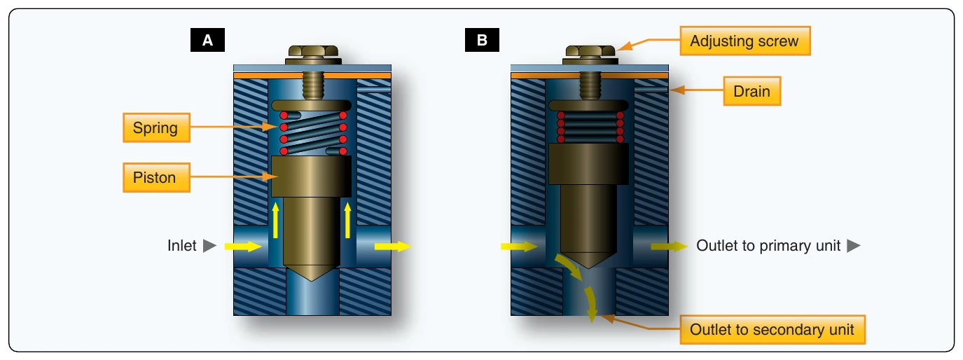
Mechanically-Operated Sequence Valve
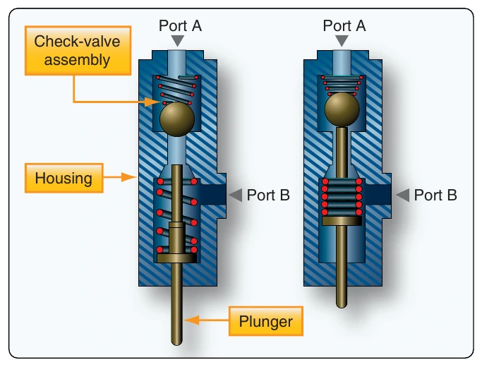
The mechanically-operated sequence valve is operated by a plunger that extends through the body of the valve. [Figure 12-40] The valve is mounted so that the plunger is operated by the primary unit. A check valve, either a ball or a poppet, is installed between the fluid ports in the body. It can be unseated by either the plunger or fluid pressure. Port A and the actuator of the primary unit are connected by a common line. Port B is connected by a line to the actuator of the secondary unit. When fluid under pressure flows to the primary unit, it also flows into the sequence valve through port A to the seated check valve in the sequence valve. In order to operate the secondary unit, the fluid must flow through the sequence valve. The valve is located so that the primary unit moves the plunger as it completes its operation. The plunger unseats the check valve and allows the fluid to flow through the valve, out port B, and to the secondary unit.
Priority Valves
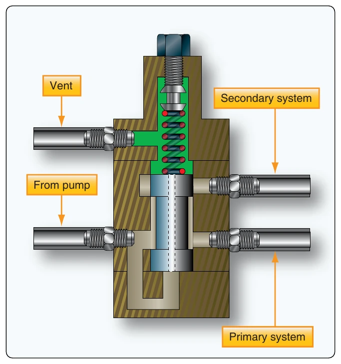
A priority valve gives priority to the critical hydraulic subsystems over noncritical systems when system pressure is low. For instance, if the pressure of the priority valve is set for 2,200 psi, all systems receive pressure when the pressure is above 2,200 psi. If the pressure drops below 2,200 psi, the priority valve closes, and no fluid pressure flows to the noncritical systems. [Figure 12-41] Some hydraulic designs use pressure switches and electrical shutoff valves to assure that the critical systems have priority over noncritical systems when system pressure is low.
Quick Disconnect Valves
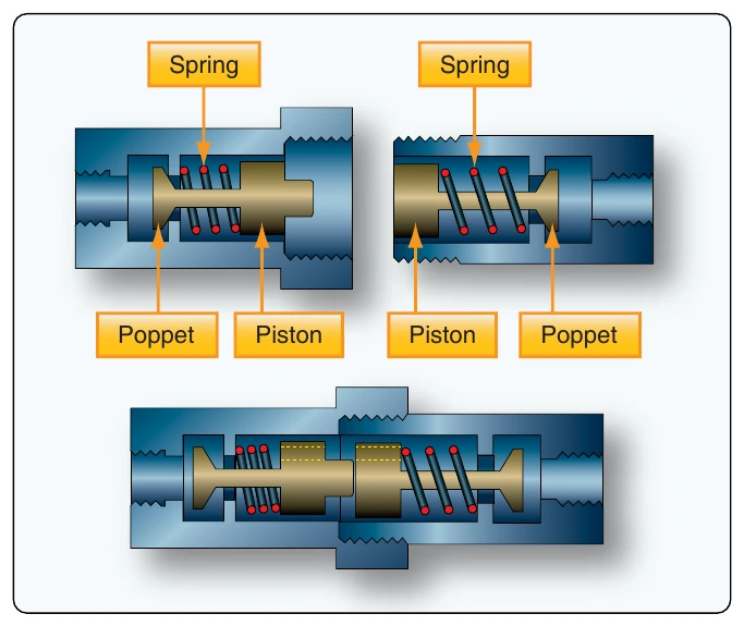
Quick disconnect valves are installed in hydraulic lines to prevent loss of fluid when units are removed. Such valves are installed in the pressure and suction lines of the system immediately upstream and downstream of the power pump. In addition to pump removal, a power pump can be disconnected from the system and a hydraulic test stand connected in its place. These valve units consist of two interconnecting sections coupled together by a nut when installed in the system. Each valve section has a piston and poppet assembly. These are spring loaded to the closed position when the unit is disconnected. [Figure 12-42]
Hydraulic Fuses
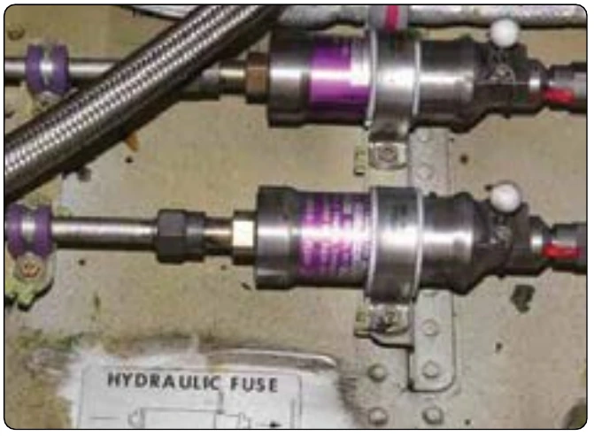
A hydraulic fuse is a safety device. Fuses may be installed at strategic locations throughout a hydraulic system. They detect a sudden increase in flow, such as a burst downstream, and shut off the fluid flow. By closing, a fuse preserves hydraulic fluid for the rest of the system. Hydraulic fuses are fitted to the brake system, leading edge flap and slat extend and retract lines, nose landing gear up and down lines, and the thrust reverser pressure and return lines. One type of fuse, referred to as the automatic resetting type, is designed to allow a certain volume of fluid per minute to pass through it. If the volume passing through the fuse becomes excessive, the fuse closes and shuts off the flow. When the pressure is removed from the pressure supply side of the fuse, it automatically resets itself to the open position. Fuses are usually cylindrical in shape, with an inlet and outlet port at opposite ends. [Figure 12-43]
Pressure Control Valves
The safe and efficient operation of fluid power systems, system components, and related equipment requires a means of controlling pressure. There are many types of automatic pressure control valves. Some of them are an escape for pressure that exceeds a set pressure; some only reduce the pressure to a lower pressure system or subsystem; and some keep the pressure in a system within a required range.
Relief Valves
Hydraulic pressure must be regulated in order to use it to perform the desired tasks. A pressure relief valve is used to limit the amount of pressure being exerted on a confined liquid. This is necessary to prevent failure of components or rupture of hydraulic lines under excessive pressures. The pressure relief valve is, in effect, a system safety valve.
The design of pressure relief valves incorporates adjustable spring-loaded valves. They are installed in such a manner as to discharge fluid from the pressure line into a reservoir return line when the pressure exceeds the predetermined maximum for which the valve is adjusted. Various makes and designs of pressure relief valves are in use, but, in general, they all employ a spring-loaded valving device operated by hydraulic pressure and spring tension. [Figure 12-44] Pressure relief valves are adjusted by increasing or decreasing the tension on the spring to determine the pressure required to open the valve. They may be classified by type of construction or uses in the system. The most common types of valve are:
- Ball type—in pressure relief valves with a ball-type valving device, the ball rests on a contoured seat. Pressure acting on the bottom of the ball pushes it off its seat, allowing the fluid to bypass.
- Sleeve type—in pressure relief valves with a sleeve-type valving device, the ball remains stationary and a sleeve-type seat is moved up by the fluid pressure. This allows the fluid to bypass between the ball and the sliding sleeve-type seat.
- Poppet type—in pressure relief valves with a poppet-type valving device, a cone-shaped poppet may have any of several design configurations; however, it is basically a cone and seat machined at matched angles to prevent leakage. As the pressure rises to its predetermined setting, the poppet is lifted off its seat, as in the ball-type device. This allows the fluid to pass through the opening created and out the return port.