
Chapter 13
Aircraft Landing Gear Systems
While aircraft brakes slow the aircraft by changing kinetic energy into heat energy, overheating of the brakes is not desirable. Excessive heat can damage and distort brake parts weakening them to the point of failure. Protocol for brake usage is designed to prevent overheating. When a brake shows signs of overheating, it must be removed from the aircraft and inspected for damage. When an aircraft is involved in an aborted takeoff, the brakes must be removed and inspected to ensure they withstood this high level of use.
The typical post-overheat brake inspection involves removal of the brake from the aircraft and disassembly of the brakes. All of the seals must be replaced. The brake housing must be checked for cracks, warping, and hardness per the maintenance manual. Any weakness or loss of heat treatment could cause the brake to fail under high-pressure braking. The brake discs must also be inspected. They must not be warped, and the surface treatment must not be damaged or transferred to an adjacent disc. Once reassembled, the brake should be bench tested for leaks and pressure tested for operation before being installed on the aircraft.
Dragging
Brake drag is a condition caused by the linings not retracting from the brake disc when the brakes are no longer being applied. It can be caused by several different factors. Brakes that drag are essentially partially on at all times. This can cause excessive lining wear and overheating leading to damage to the disc(s).
A brake may drag when the return mechanism is not functioning properly. This could be due to a weak return spring, the return pin slipping in the auto adjuster pin grip, or similar malfunction. Inspect the auto adjuster(s) and return units on the brake when dragging is reported. An overheated brake that has warped the disc also causes brake drag. Remove the brake and perform a complete inspection as discussed in the previous section. Air in the brake fluid line can also cause brake drag. Heat causes the air to expand, which pushes the brake linings against the disc prematurely. If no damage has been caused when reported, bleed the brakes to remove the air from the system to eliminate the drag.
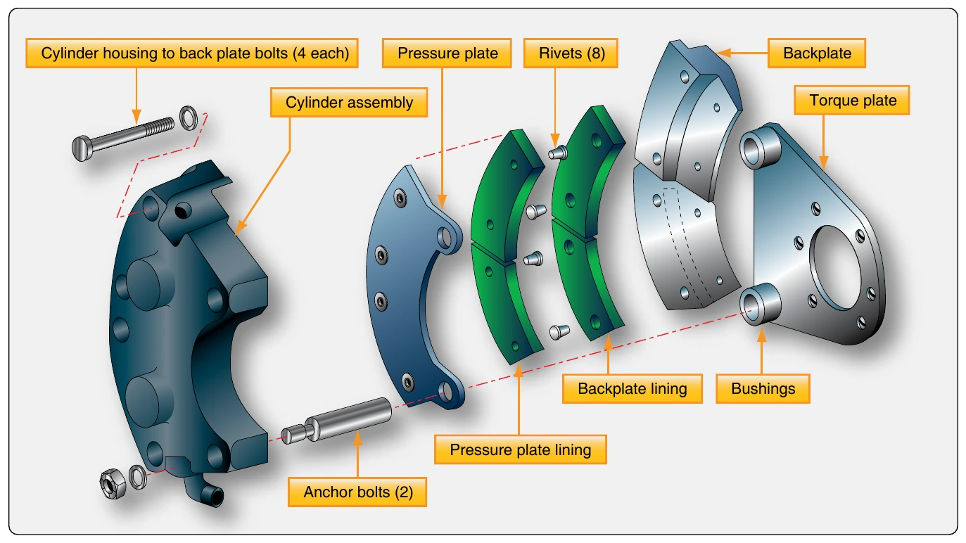
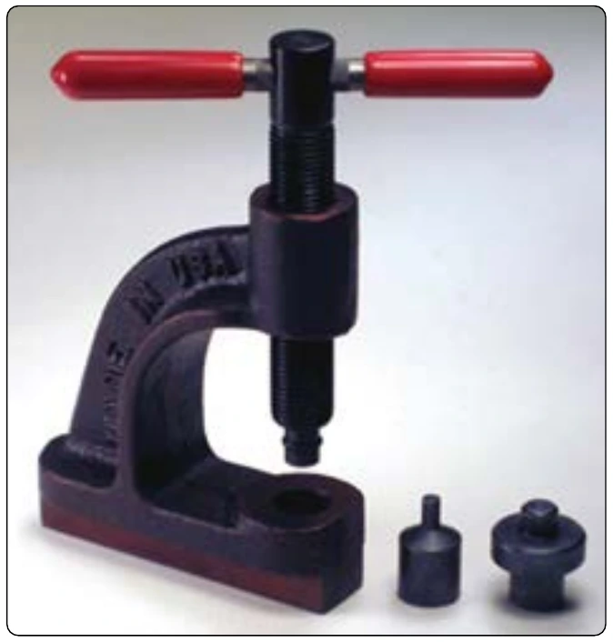
At all times, the technician should perform inspections to ensure the proper parts are used in the brake assembly. Improper parts, especially in the retraction/adjuster assemblies, can cause the brakes to drag.
Chattering or Squealing
Brakes may chatter or squeal when the linings do not ride smoothly and evenly along the disc. A warped disc(s) in a multiple brake disc stack produces a condition wherein the brake is actually applied and removed many times per minute. This causes chattering and, at high frequency, it causes squealing. Any misalignment of the disc stack out of parallel causes the same phenomenon. Discs that have been overheated may have damage to the surface layer of the disc. Some of this mix may be transferred to the adjacent disc resulting in uneven disc surfaces that also leads to chatter or squeal. In addition to the noise produced by brake chattering and squealing, vibration is caused that may lead to further damage of the brake and the landing gear system. The technician must investigate all reports of brake chattering and squealing.
Aircraft Tires & Tubes
Aircraft tires may be tube-type or tubeless. They support the weight of the aircraft while it is on the ground and provide the necessary traction for braking and stopping. The tires also help absorb the shock of landing and cushion the roughness of takeoff, rollout, and taxi operations. Aircraft tires must be carefully maintained to perform as required. They accept a variety of static and dynamic stresses and must do so dependably in a wide range of operating conditions.
Tire Classification
Aircraft tires are classified in various ways including by: type, ply rating, whether they are tube-type or tubeless, and whether they are bias ply tires or radials. Identifying a tire by its dimensions is also used. Each of these classifications is discussed as follows.
Types
A common classification of aircraft tires is by type as classified by the United States Tire and Rim Association. While there are nine types of tires, only Types I, III, VII, and VIII, also known as a Three-Part Nomenclature tires, are still in production.
Type I tires are manufactured, but their design is no longer active. They are used on fixed gear aircraft and are designated only by their nominal overall diameter in inches. These are smooth profile tires that are obsolete for use in the modern aviation fleet. They may be found on older aircraft.
Type III tires are common general aviation tires. They are typically used on light aircraft with landing speeds of 160 miles per hour (mph) or less. Type III tires are relatively low-pressure tires that have small rim diameters when compared to the overall width of the tire. They are designed to cushion and provide flotation from a relatively large footprint. Type III tires are designated with a two-number system. The first number is the nominal section width of the tire, and the second number is the diameter of the rim the tire is designed to mount upon. [Figure 13-126]
Type VII tires are high performance tires found on jet aircraft. They are inflated to high-pressure and have exceptional high load carrying capability. The section width of Type VII tires is typically narrower than Type III tires. Identification of Type VII aircraft tires involves a two-number system. An X is used between the two numbers. The first number designates the nominal overall diameter of the tire. The second number designates the section width. [Figure 13-127]
Type VIII aircraft tires are also known as three-part nomenclature tires. [Figure 13-128] They are inflated to very high-pressure and are used on high-performance jet aircraft. The typical Type VIII tire has relatively low profile and is capable of operating at very high speeds and very high loads. It is the most modern design of all tire types. The three-part nomenclature is a combination of Type III and Type VII nomenclature where the overall tire diameter, section width, and rim diameter are used to identify the tire. The X and “–” symbols are used in the same respective positions in the designator.