
Chapter 13
Aircraft Landing Gear Systems
- Construct and attach a bleed hose containing a fitting suitable for making an airtight connection at the shock strut service valve port. Ensure a long enough hose to reach the ground while the aircraft is on jacks.
- Jack the aircraft until the shock struts are fully extended.
- Release any air pressure in the shock strut.
- Remove the air service valve assembly.
- Fill the strut to the level of the service port with approved hydraulic fluid.
- Attach the bleed hose to the service port and insert the free end of the hose into a container of clean hydraulic fluid. The hose end must remain below the surface of the fluid.
- Place an exerciser jack or other suitable jack under the shock strut jacking point. Compress and extend the strut fully by raising and lowering the jack. Continue this process until all air bubbles cease to form in the container of hydraulic fluid. Compress the strut slowly and allow it to extend by its own weight. Ensure that the hydraulic fluid is still at the appropriate level before moving on to the next step.
- Remove the exerciser jack. Lower the aircraft and remove all other jacks.
- Remove the bleed hose assembly and fitting from the service port of the strut.
- Install the air service valve, torque, and inflate the shock strut to the manufacturer’s specifications.
Landing Gear Alignment, Support, & Retraction
Retractable landing gear consist of several components that enable it to function. Typically, these are the torque links, trunnion and bracket arrangements, drag strut linkages, electrical and hydraulic gear retraction devices, as well as locking, sensing, and indicating components. Additionally, nose gear have steering mechanisms attached to the gear.
Alignment
As previously mentioned, a torque arm or torque links assembly keeps the lower strut cylinder from rotating out of alignment with the longitudinal axis of the aircraft. In some strut assemblies, it is the sole means of retaining the piston in the upper strut cylinder. The link ends are attached to the fixed upper cylinder and the moving lower cylinder with a hinge pin in the center to allow the strut to extend and compress.
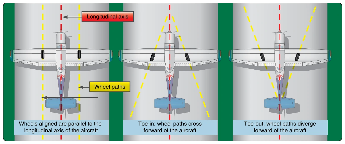
Alignment of the wheels of an aircraft is also a consideration. Normally, this is set by the manufacturer and only requires occasional attention such as after a hard landing. The aircraft’s main wheels must be inspected and adjusted, if necessary, to maintain the proper toe-in or toe-out and the correct camber. Toe-in and toe-out refer to the path a main wheel would take in relation to the airframe longitudinal axis or centerline if the wheel was free to roll forward. Three possibilities exist. The wheel would roll either: 1) parallel to the longitudinal axis (aligned); 2) converge on the longitudinal axis (toe-in); or 3) veer away from the longitudinal axis (toe-out). [Figure 13-28]
The manufacturer’s maintenance instructions give the procedure for checking and adjusting toe-in or toe-out. A general procedure for checking alignment on a light aircraft follows. To ensure that the landing gear settle properly for a toe-in/toe-out test, especially on spring steel strut aircraft, two aluminum plates separated with grease are put under each wheel. Gently rock the aircraft on the plates to cause the gear to find the at rest position preferred for alignment checks.
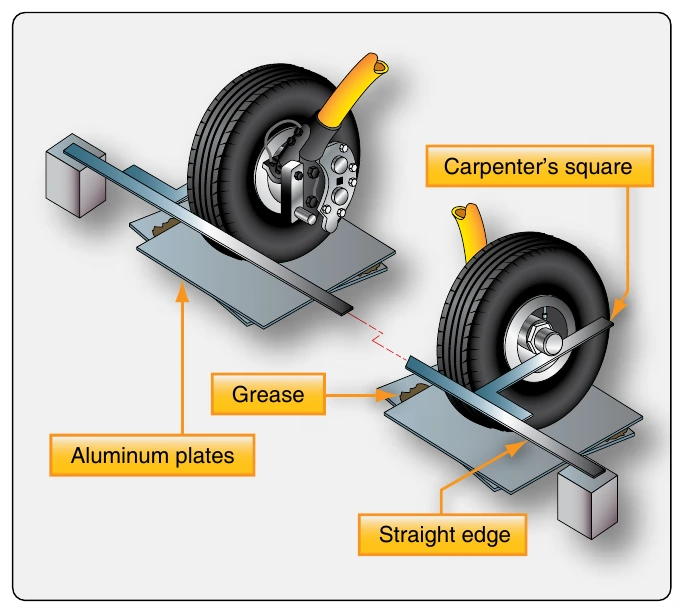
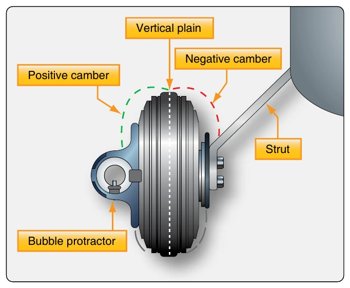
A straight edge is held across the front of the main wheel tires just below axle height. A carpenter’s square placed against the straight edge creates a perpendicular that is parallel to the longitudinal axis of the aircraft. Slide the square against the wheel assembly to see if the forward and aft sections of the tire touch the square. A gap in front indicates the wheel is toed-in. A gap in the rear indicates the wheel is toed-out. [Figure 13-29] Camber is the alignment of a main wheel in the vertical plain. It can be checked with a bubble protractor held against the wheel assembly. The wheel camber is said to be positive if the top of the wheel tilts outward from vertical. Camber is negative if the top of the wheel tilts inward. [Figure 13-30]
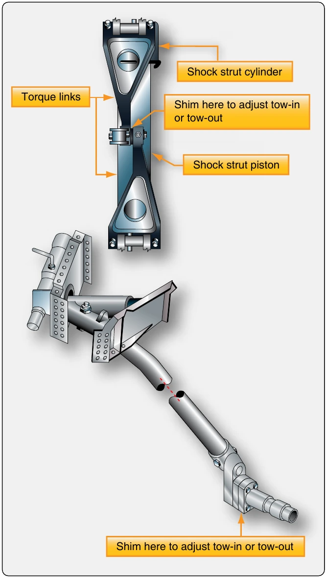
Adjustments can be made to correct small amounts of wheel misalignment. On aircraft with spring steel gear, tapered shims can be added or removed between the bolt-on wheel axle and the axle mounting flange on the strut. Aircraft equipped with air/oil struts typically use shims between the two arms of the torque links as a means of aligning toe-in and toe-out. [Figure 13-31] Follow all manufacturer’s instructions.
Support
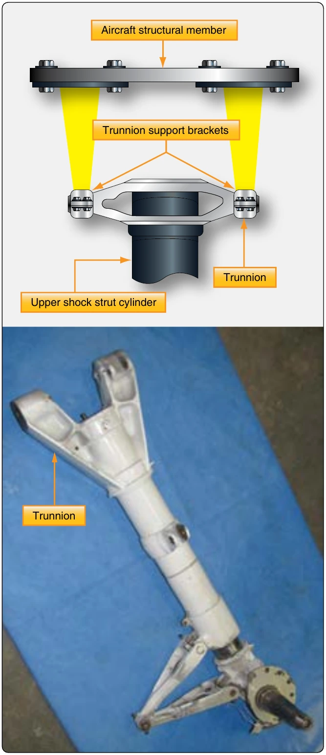
Aircraft landing gear are attached to the wing spars or other structural members, many of which are designed for the specific purpose of supporting the landing gear. Retractable gear must be engineered in such a way as to provide strong attachment to the aircraft and still be able to move into a recess or well when stowed. A trunnion arrangement is typical. The trunnion is a fixed structural extension of the upper strut cylinder with bearing surfaces that allow the entire gear assembly to move. It is attached to aircraft structure in such a way that the gear can pivot from the vertical position required for landing and taxi to the stowed position used during flight. [Figure 13-32]
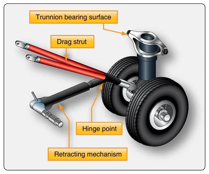
While in the vertical gear down position, the trunnion is free to swing or pivot. Alone, it cannot support the aircraft without collapsing. A drag brace is used to restrain against the pivot action built into the trunnion attachment. The upper end of the two-piece drag brace is attached to the aircraft structure and the lower end to the strut. A hinge near the middle of the brace allows the brace to fold and permits the gear to retract. For ground operation, the drag brace is straightened over center to a stop and locked into position so the gear remains rigid. [Figure 13-33] The function of a drag brace on some aircraft is performed by the hydraulic cylinder used to raise and lower the gear. Cylinder internal hydraulic locks replace the over-center action of the drag brace for support during ground maneuvers.
Small Aircraft Retraction Systems
As the speed of a light aircraft increases, there reaches a point where the parasite drag created by the landing gear in the wind is greater than the induced drag caused by the added weight of a retractable landing gear system. Thus, many light aircraft have retractable landing gear. There are many unique designs. The simplest contains a lever in the flight deck mechanically linked to the gear. Through mechanical advantage, the pilot extends and retracts the landing gear by operating the lever. Use of a roller chain, sprockets, and a hand crank to decrease the required force is common.