
Chapter 16
Cabin Environmental Control Systems
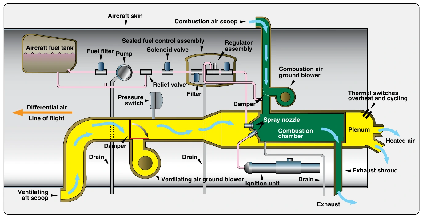
The air used in the combustion process is ambient air scooped from outside the aircraft, or from the compartment in which the combustion heater is mounted. A blower ensures that the correct quantity and pressure of air are sent into the chamber.
Some units have regulators or a relief valve to ensure these parameters. The combustion air is completely separate from the air that is warmed and sent into the cabin.
Ventilating Air System
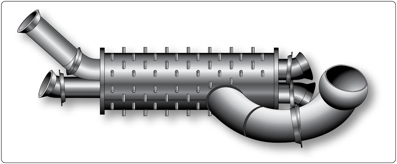
Ventilating air is the name of the air that is warmed and sent into the cabin. Typically, it comes into the combustion heater through a ram air intake. When the aircraft is on the ground, a ventilating air fan controlled by a landing gear squat switch operates to draw in the air. Once airborne, the fan ceases to operate as the ram air flow is sufficient. Ventilating air passes between the combustion chamber and the outer shroud of the combustion heater where it is warmed and sent to the cabin.
Fuel System
As mentioned, fuel for the combustion heater is drawn from an aircraft fuel tank. A constant pressure fuel pump with relief valve pulls the fuel through a filter. A main solenoid valve downstream delivers the fuel to the unit. The solenoid is controlled by the cabin heater switch in the flight deck and three safety switches located on the combustion heater. The first safety switch is a duct limit switch that keeps the valve closed should the unit not have enough ventilating airflow to keep it within the correct operating temperature range. The second is a pressure switch that must sense pressure from the combustion air fan to allow the solenoid to open. Fuel is delivered to the combustion chamber only if there is air there with which it can be mixed. Finally, an overheat switch also controls the main fuel supply solenoid. When an over temperature condition occurs, it closes the solenoid to stop the supply of fuel.
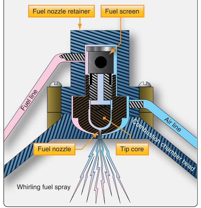
A secondary solenoid is located downstream of the main fuel supply solenoid. It is part of a fuel control unit that also houses a pressure regulator and an additional fuel filter. The valve opens and closes on command from the combustion heater thermostat. During normal operation, the heater cycles on and off by opening and closing this solenoid at the entrance to the combustion chamber. When opened, fuel flows through a nozzle that sprays it into the combustion chamber. [Figure 16-100]
Ignition System
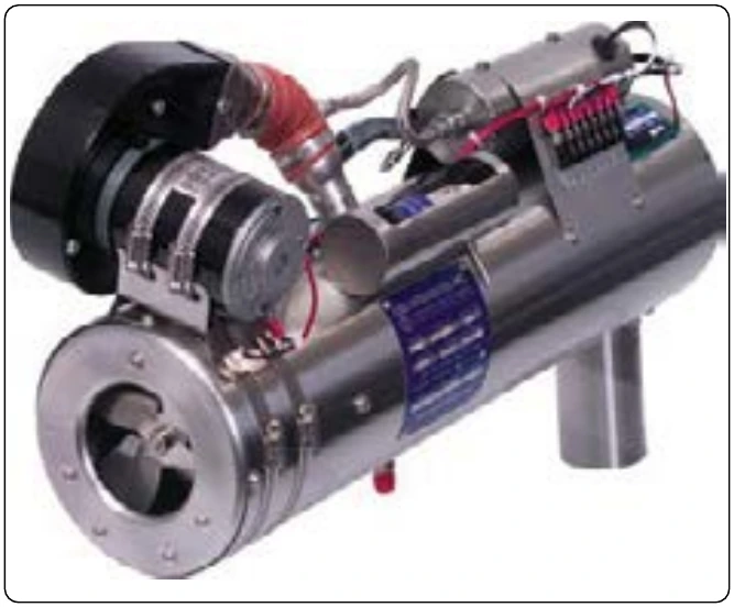
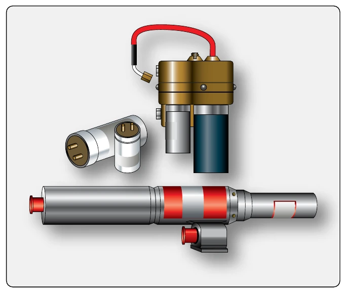
Most combustion heaters have an ignition unit designed to receive aircraft voltage and step it up to fire a spark plug located in the combustion chamber. Older combustion heaters use vibrator-type ignition units. Modern units have electronic ignition. [Figure 16-101] The ignition is continuous when activated. This occurs when the heater switch is placed in the ON position in the flight deck, and the combustion air blower builds sufficient air pressure in the combustion chamber. Use of the proper spark plug for the combustion heater is essential. Check the manufacturer’s approved data. [Figure 16-102]
Controls
The combustion heater controls consist of a cabin heat switch and a thermostat. The cabin heat switch starts the fuel pump, opens the main fuel supply solenoid, and turns on the combustion air fan, as well as the ventilating air fan if the aircraft is on the ground. When the combustion air fan builds pressure, it allows the ignition unit to start. The thermostat sends power to open the fuel control solenoid when heat is needed. This triggers combustion in the unit and heat is delivered to the cabin. When the preselected temperature is reached, the thermostat cuts power to the fuel control solenoid and combustion stops. Ventilating air continues to circulate and carry heat away. When the temperature level falls to that below which the thermostat is set, the combustion heater cycles on again.
Safety Features
Various automatic combustion heater controls prevent operation of the heater when dangerous conditions exist. As stated, a duct limit switch cuts off fuel to the heater when there is not enough airflow to keep the heater duct below a preset temperature. This is usually caused by a lack of ventilating air flow. An overheat switch set at a higher temperature than the duct limit switch guards against overheat of any kind. It is designed to cut fuel to the combustion heater before an unwanted fire occurs. When this switch activates, a light is illuminated in the flight deck and the heater cannot be restarted until maintenance determines the cause. Some heaters contain a circuit to prevent fuel from being delivered to the combustion chamber if the ignition system is not working.
Maintenance & Inspection
Maintenance of combustion heaters consists of routine items, such as cleaning filters, checking spark plug wear, and ensuring inlets are not plugged. All maintenance and inspection of combustion heaters should be accomplished in accordance with the aircraft manufacturer’s instructions. Combustion heater manufacturers also produce maintenance guidelines that should be followed. Intervals between the performance of maintenance items and the time between overhauls must be followed to help ensure a properly functioning heater is available when it is needed.