Chapter 4
Aircraft Metal Structural Repair
A damaged leading edge usually involves several structural parts. FOD probably involves the nose skin, nose ribs, stringers, and possibly the cap strip. Damage involving all of these members necessitates installing an access door to make the repair possible. First, the damaged area has to be removed and repair procedures established. The repair needs insertions and splice pieces. If the damage is serious enough, it may require repair of the cap strip and stringer, a new nose rib, and a skin panel. When repairing a leading edge, follow the procedures prescribed in the appropriate repair manual for this type of repair. [Figure 4-192] Repairs to leading edges are more difficult to accomplish than repairs to flat and straight structures because the repair parts need to be formed to fit the existing structure.
Trailing Edge Repair
A trailing edge is the rear-most part of an airfoil found on the wings, ailerons, rudders, elevators, and stabilizers. It is usually a metal strip that forms the shape of the edge by tying the ends of a rib section together and joining the upper and lower skins. Trailing edges are not structural members, but they are considered to be highly stressed in all cases.
Damage to a trailing edge may be limited to one point or extended over the entire length between two or more rib sections. Besides damage resulting from collision and careless handling, corrosion damage is often present. Trailing edges are particularly subject to corrosion because moisture collects or is trapped in them.
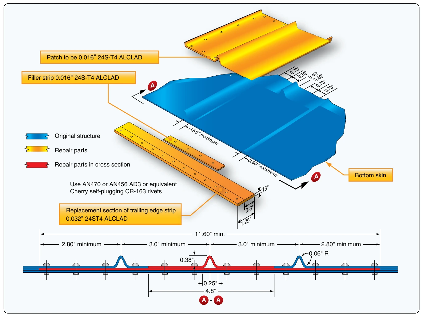
Thoroughly inspect the damaged area before starting repairs, and determine the extent of damage, the type of repair required, and the manner in which the repair should be performed. When making trailing edge repairs, remember that the repaired area must have the same contour and be made of material with the same composition and temper as the original section. The repair must also be made to retain the design characteristics of the airfoil. [Figure 4-193]
Specialized Repairs
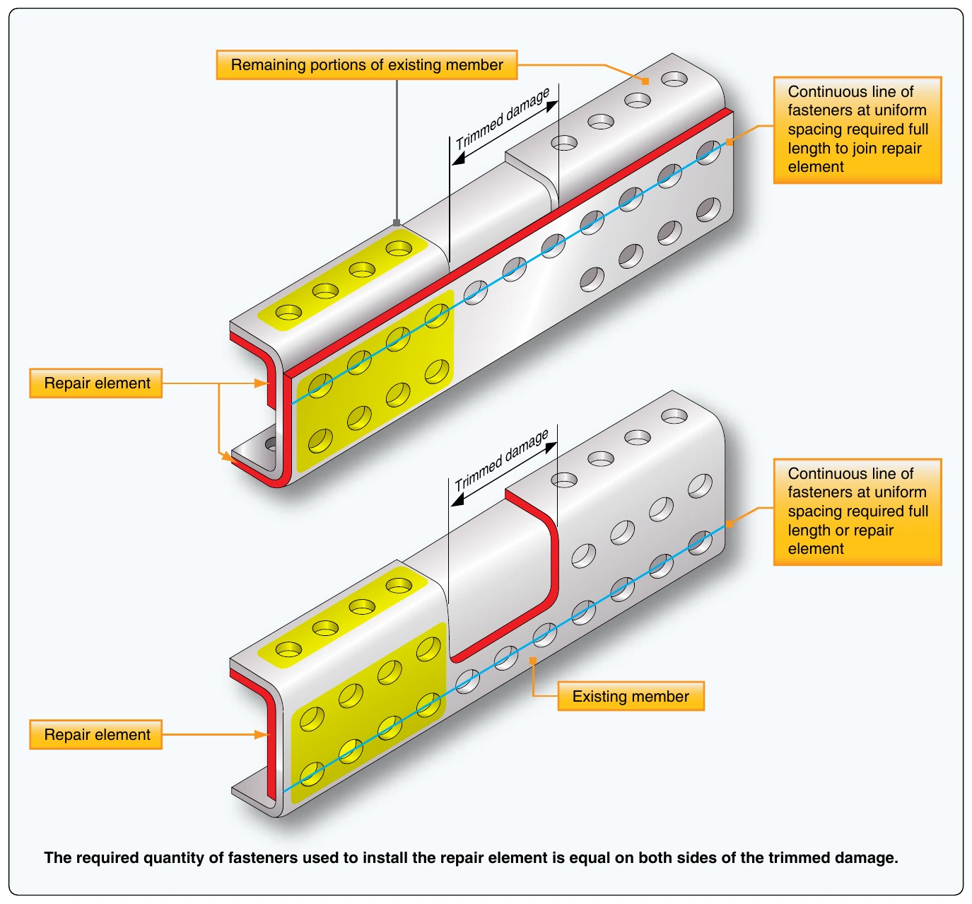
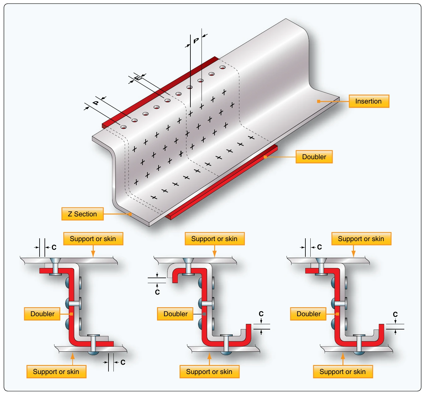
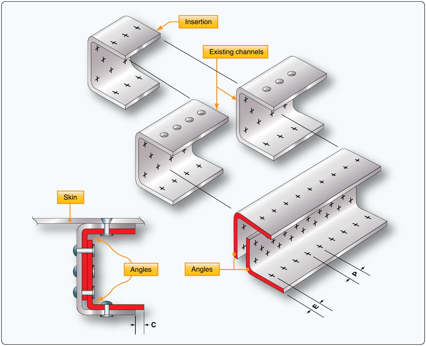
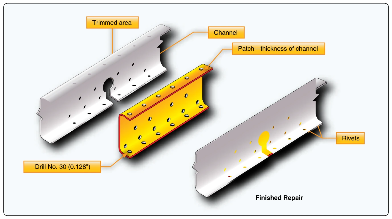
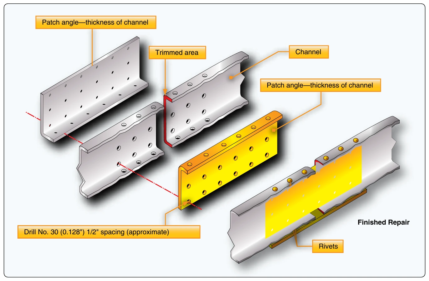
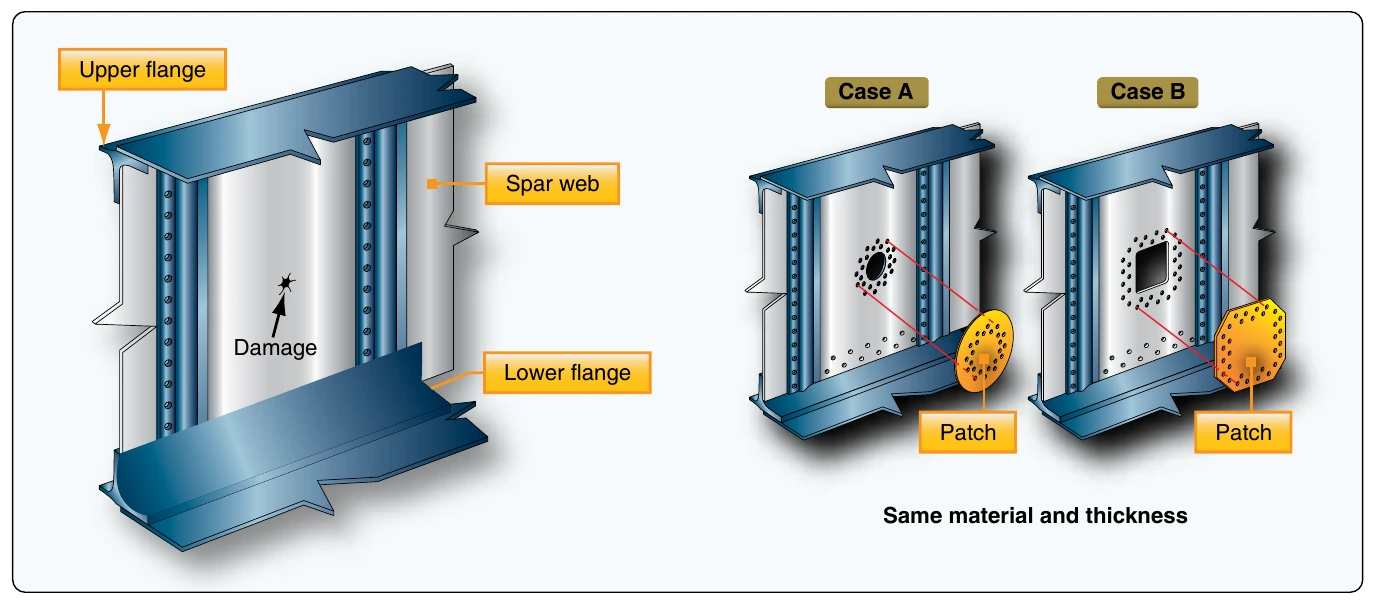
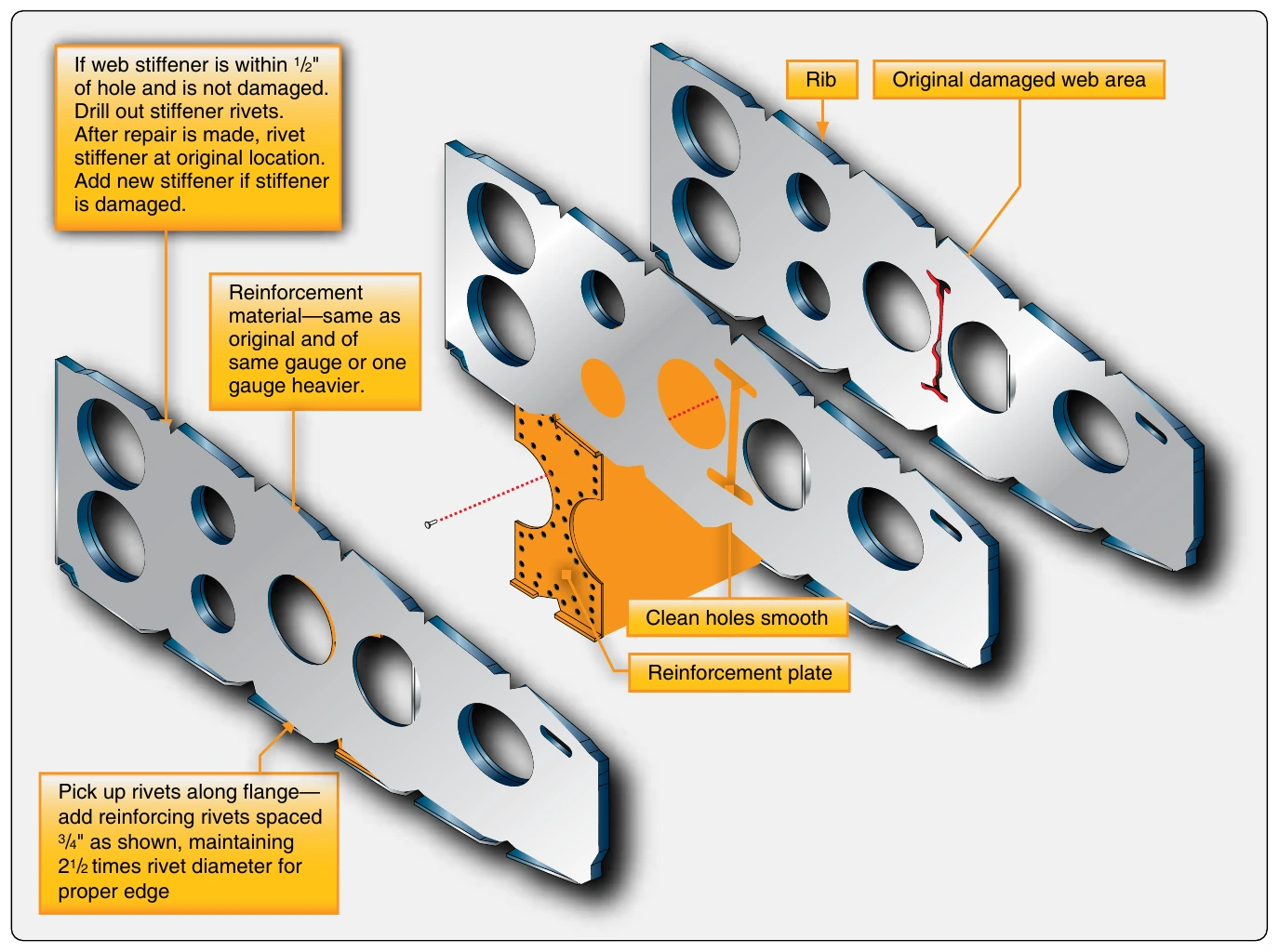
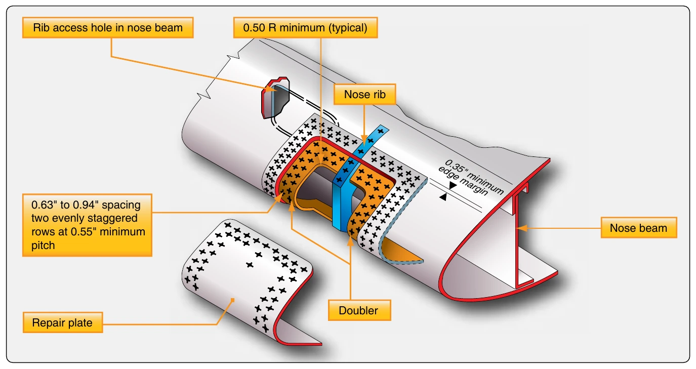
Figures 4-194 through 4-198 are examples of repairs for various structural members. Specific dimensions are not included since the illustrations are intended to present the basic design philosophy of general repairs rather than be used as repair guidelines for actual structures. Remember to consult the SRM for specific aircraft to obtain the maximum allowable damage that may be repaired and the suggested method for accomplishing the repair.
Inspection Openings
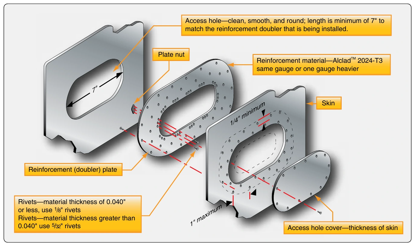
If it is permitted by the applicable aircraft maintenance manual, installation of a flush access door for inspection purposes sometimes makes it easier to repair the internal structure as well as damage to the skin in certain areas. This installation consists of a doubler and a stressed cover plate.
A single row of nut plates is riveted to the doubler, and the doubler is riveted to the skin with two staggered rows of rivets. [Figure 4-199] The cover plate is then attached to the doubler with machine screws.